Can Crusher Part 1 - Building the Frame
I have some free time so I decided to do a project for fun where the goal was to build something from start-to-finish, doing as much as possible. All my public projects are software-only. Now that I’m doing more stuff with robotics, hardware, and consumer products, I thought it would be nice to do something to showcase all of those skills.
The project is an aluminum can crusher. Not just any crusher, but the most technologically advanced robotic can crusher the world has ever seen!
I hope to:
- Design all the structural elements myself in a CAD program.
- Fabricate it all in-house (literally my house) with 3D printing, CNC, etc.
- Design a custom interface to control stepper motor drivers from a RP2040, aka Raspberry Pi Pico.
- Design a PCB myself to hold the Pi Pico, Stepper Drivers, and associated electronics.
- Get the PCB manufactured and assemble it in-house.
- Provide a complete slick industrial-yet-commercial looking product.
My biggest concern is wondering if the thing will actually have enough power to crush cans. But we’ll worry about that later. For now, the frame…
Basic Goals for the Frame
-
Do a serious CAD project in FreeCAD.
- Don’t just make everything a 3D print:
- Use Aluminum Extrusions for the frame.
- Use CNCed Acrylic for the frame ends for additional strength, and to get experience with a home CNC machine I own but haven’t really used yet.
-
Use affordable over-the-counter hardware, nothing too extravagant.
- Provide files so someone else can print and build.
FreeCAD
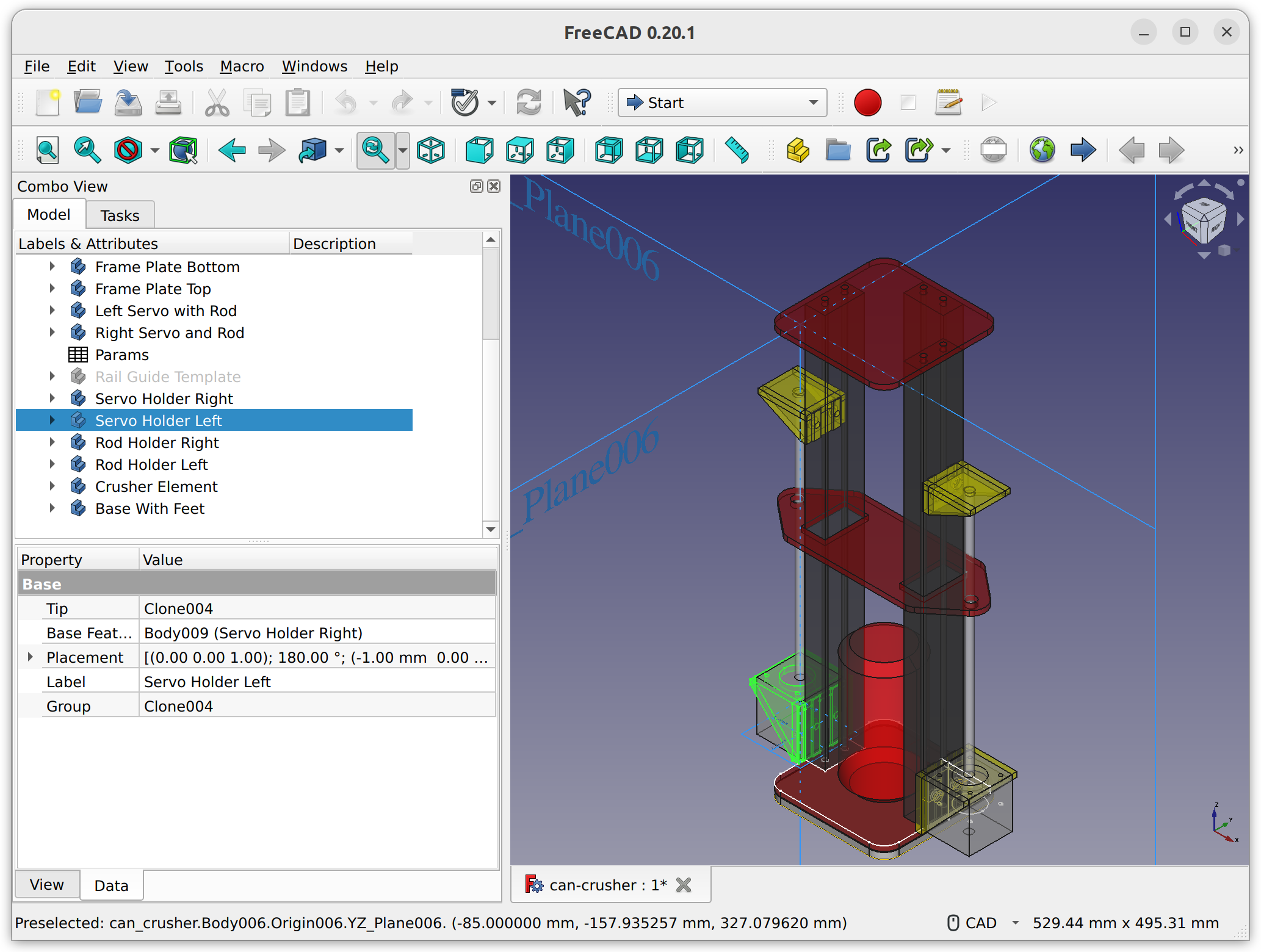
In that past I’ve used OpenSCAD for personal projects but had mixed feelings about it. As things got more complex it was hard for me to visualize and build out objects in code. I decided I would give FreeCAD a try for this project.
I’d briefly tried using it without much success in the past. The recommended tutorial didn’t click and it was unclear how I’d turn the result of a sketch in to a working project. I was probably too hasty. This time I found an excellent series of video tutorials from Flowwie that were enough to get up to speed and hit the ground running. I was surprised how quickly I was able to build out all the parts and generate STLs for 3d Printing.
Aluminum Extrusions
I bought 3 400mm pre-cut 2040 Aluminum Extrusions to provide most of the strength for the frame. These are easy to find on Amazon/eBay/Ali-Express and I think I’ll be using them more in the future.
The only trouble is that the holes at the ends of the extrusions aren’t pre-threaded like they would be in a 3D printer kit. That’s easy enough to fix with a $10 screw tapping kit with a M5 sized tap. On my 2040 extrusions the hole was already a decent size. There was no need to drill a pilot hole before using the tap.
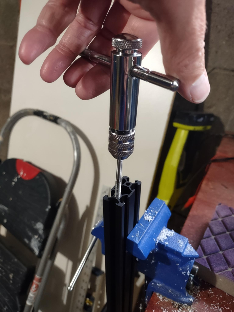
It requires surprisingly little force to tap the ends. The tap will be a little loose at first since it’s tapered to make it easy to get started. Once the tap is past the tapered part and not wobbling, I just kept twisting one full revolution to thread, then one half revolution back to clear out the aluminum you just cut. The aluminum is surprisingly soft and can even clump together in balls almost as if it’s melted together.
ProTip™: If you start to feel more resistance while tapping, don’t power through it! Unscrew the tap a few times. If that still feels stiff go back-and-forth in the already-threaded area quickly a few times. That should dislodge any fragments of aluminum and let you resume tapping.
3D Prints
The 3D Printing was straight-forward for me. I’ve done plenty of that before. I used PETG to get better strength than PLA. Really the only trick was to make test prints when testing things like screw hole size and position. Then I could test in 20 minutes instead of waiting 3 hours to find out things were misaligned by 1 mm.
CNC
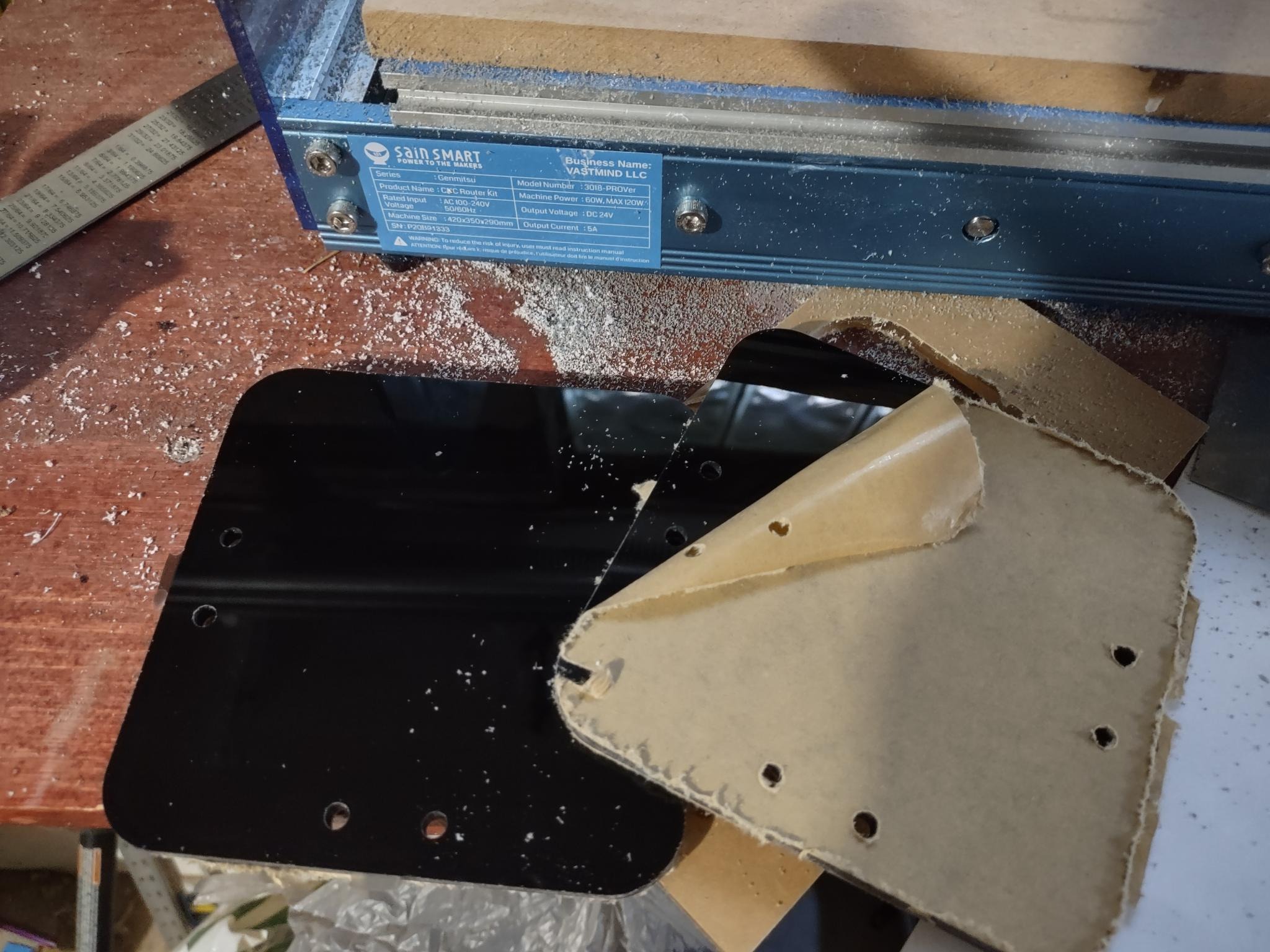
I bought a Genmitsu 3018 PROVER a bit ago that I hadn’t put to much use. I decided I would use that to mill out a few plates from acrylic instead of 3D printing. 3D printed parts aren’t always the strongest. I wanted something more solid than a layered 3D print.
The CNC machine takes a .gcode file, but it’s different enough from 3D printing that I needed to use a different program to generate it than I use for my 3D prints. FreeCAD has a Path Workbench that is supposed to generate good code for CNC purposes. I decided to go with that.
Unfortunately, I lost a day trying to use FreeCAD 20.1 to generate the required gcode. There were all sorts of problems on multiple machines, hard crashes, etc. This was a real shame because in general I can’t recommend FreeCAD enough. Its a great product. Hopefully the bugs will get worked out. Until then, I was able to use FreeCAD 19.04 to keep moving. I exported .step files and imported them in to a clean FreeCAD 19.04 project on a different computer.
The next problem was that some test parts had dimensions that were off by a half millimeter or so. Since this controls the positioning of the aluminum extrusions, it’s critical that the dimensions be correct. After some debugging I determined the CNC simply required manual calibration since it still had its out-of-the-box settings. After measuring expected vs actual movement I needed to change the steps-per-millimeter settings from the default 800 to about 794.5 for both the X and Y axis. That’s about 0.5% error but it does add up over 100 or 200 mm.
After that it was smooth sailing and my CNC was just big enough to profile out all the parts. And the screw holes lined up perfectly with a 3D printed base with feet that went under the bottom frame holder.
Assembly
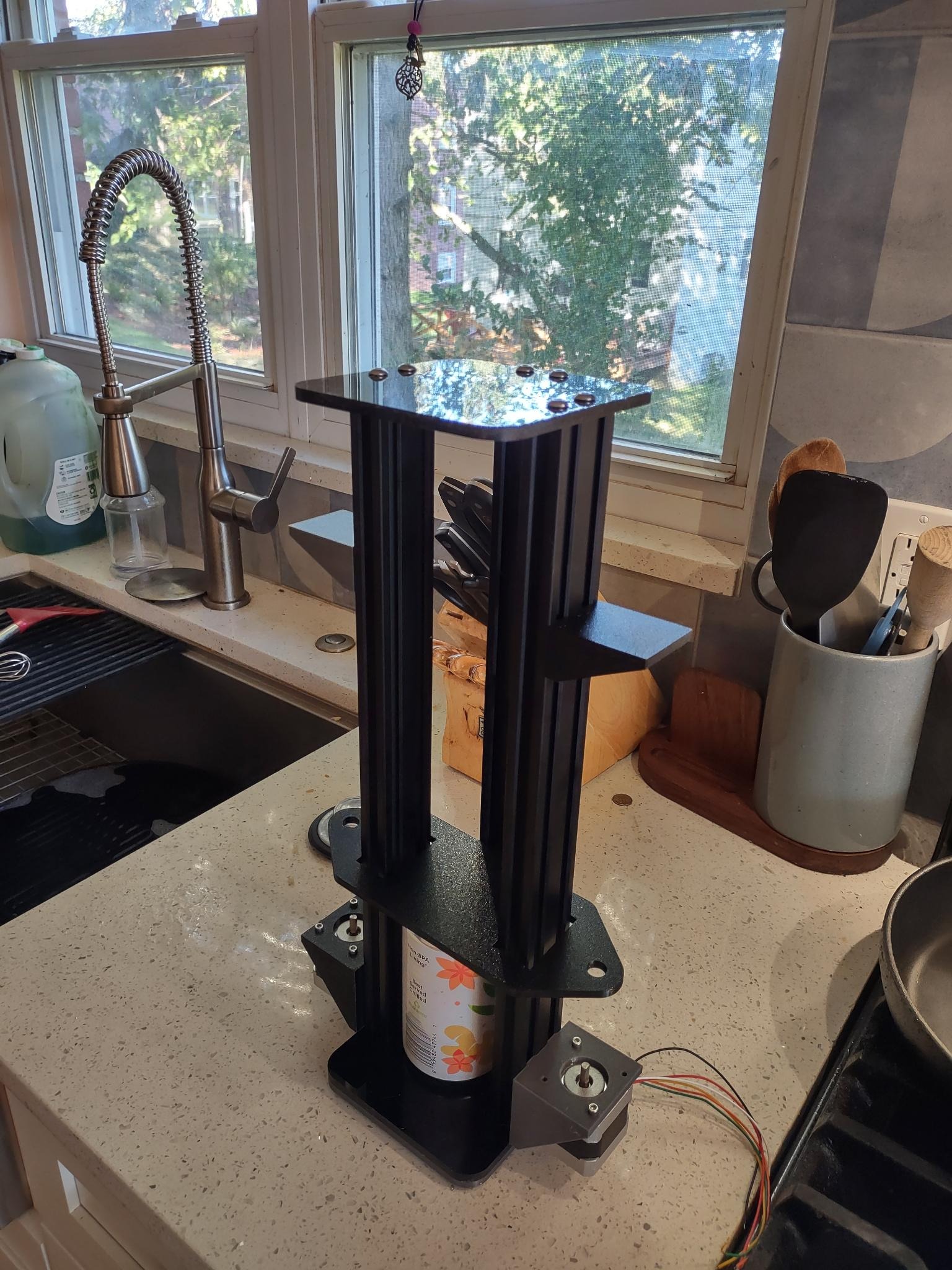
Assembly was straight forward. Just put the parts together and secure with M5 bolts, either directly in to the tapped aluminum extrusions, or with some T-Slot Nuts to position things on the length of the rails. Having a printed base under the structural acrylic with the bolts running through both worked better than expected. I attached some NEMA 17 stepper motors temporarily to the motor holders with some M3 bolts to verify the design.
The results:
Next up…
A proof of concept stepper motor driver powered by a Raspberry Pi Pico and some TMC2209 driver boards. These should drive the stepper motors. I chose TMC2209 drivers so I could try to create a self-homing machine. This avoids annoying mechanical limit switches that are difficult to position correctly.
All cad files, electronic files, source code, etc, referenced in this post series is available on my github page.