Can Crusher Part 2 - Stepper Drivers and Controls
Now that I’ve built a frame for my can crusher, the next big task is to write out the drivers to control the stepper motors and test things out. At this point everything will be on a breadboard. The goal is to make sure I know how the driver boards work, and test out the motors. It is not the production-level implementation yet.
Basic Design
- Two independent stepper motors are on each side of the unit.
- On boot the device should home by going down until the base of the unit is identified by both stepper motors.
- From there move up X mm to make space for a can.
- When can is detected, lower and crush the can.
- There will probably be additional logic when we first touch the can and feel resistance.
Motor Controller boards
I decided to use some TMC2209 driver boards manufactured by BigTreeTech. These are built for 3D printers and CNC machines and have a configuration that allows you to plug them in to the existing control boards for these machines. I’m going to use these driver boards but create my main control board from scratch.
The TMC2209 was chosen because it has built in stall-detection, and I’m hoping to get auto-homing, like you see on higher end 3D printers like Prusas. I’ll detect the end of the range of motion when stall detection kicks in.
The cheap solution is to install limit switches that are just some bits of ribbon wire that gets physically pressed to complete a circuit. These are okay, but I find them annoying because they usually act as a proxy for the actual limit, aren’t so accurate, and can move a little bit over time. The stall detection approach is much more elegant.
I’m also anticipating a stall when the plate initially hits the can so if that’s the case I’ll also be able to detect when we are held up on a can and not actually hitting the base of the unit.
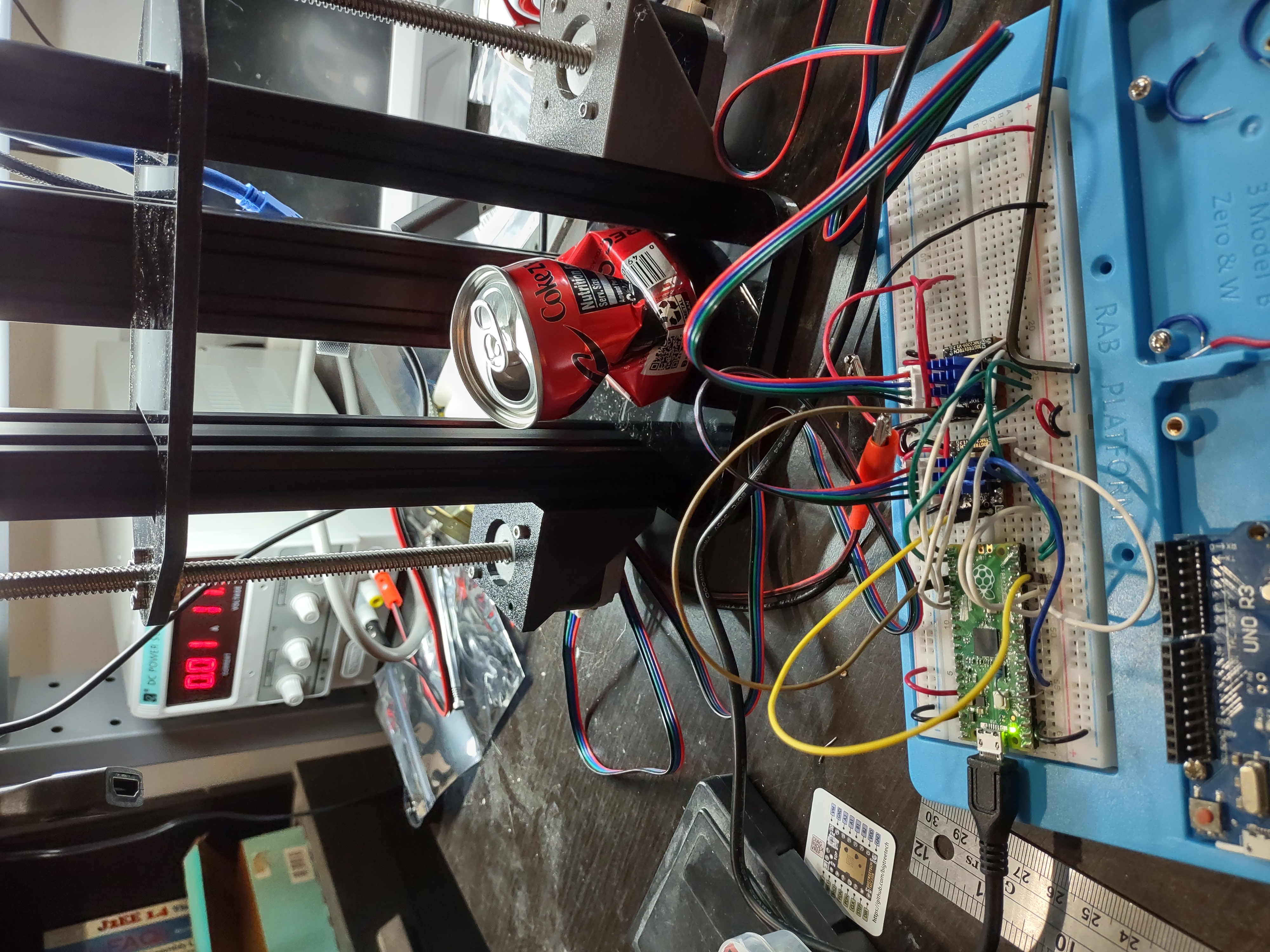
Initial Verification
I wanted to test out the boards before hooking up to my Pi Pico. The simplest possible working configuration should be:
- A stepper motor is hooked up.
- Power is applied to both the control portion and the motor portion, probably at different voltages.
- A variety of pins need to be set to either GND or VCC to enable desired behavior.
- A steady clock signal should be applied to the STEP pin and we should see the motor move.
This is a good example where accumulating gear over the years helps out. In my earlier days I would have skipped this step and gone straight to hooking up to my Pico (or Arduino, etc) and would bang my head against the wall until things worked. I also would have done something silly to deal with the fact that the motors have different power requirements than the logic portion of the board, like connecting a nine-volt battery. And then when things didn’t work I would never know if the problem was on the software side or hardware side. There would be too many variables to make debugging easy.
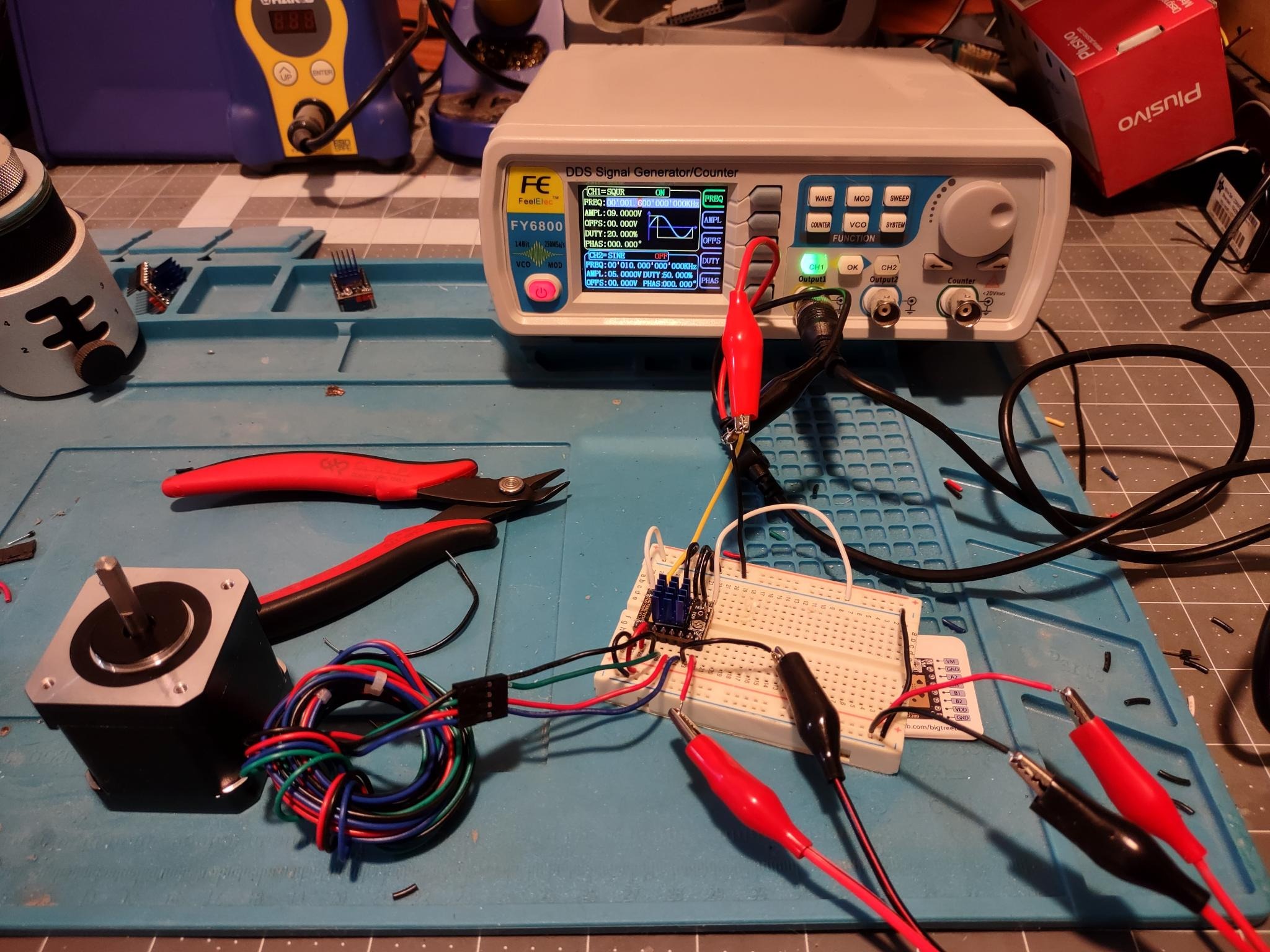
With a bench power supply and a signal generator I was able to create an initial test rig that didn’t require any microprocessor or any coding. I sent 5 volts to the VCC, 9 volts to the VM (Voltage Motor) pin, and did some quick math to determine that I wanted my signal generator to send out a square wave at 1600 Hz to rotate the motor at one Revolution Per Second. (Test motor specs indicate 1.8 degrees rotation per step, 200 steps for a full circle, and the TMC2209 defaults to 8 sub-steps, so 200 * 8 = 1600)
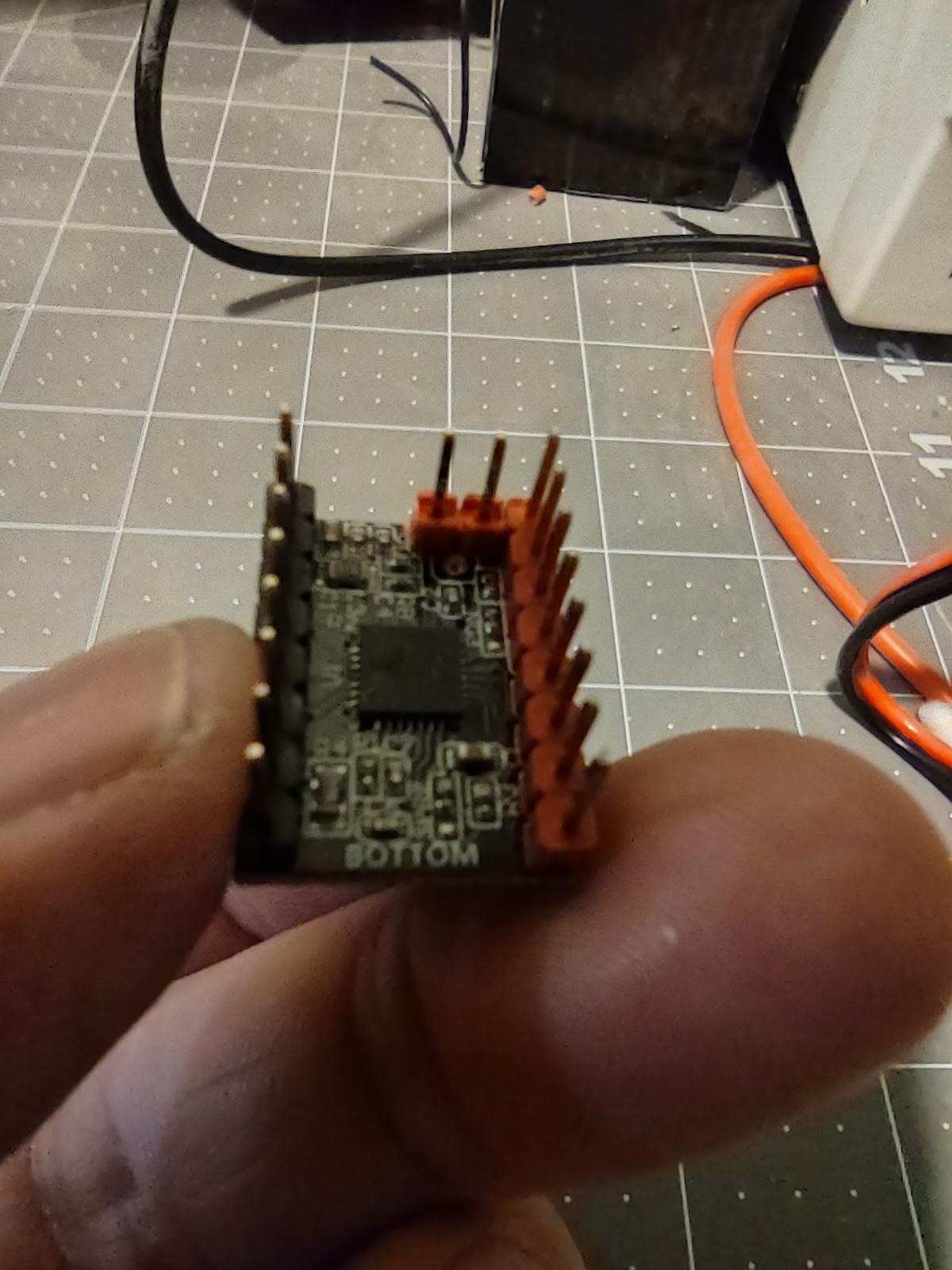
Annoyingly the BigTreeTech boards have a pin configuration that won’t let you plug them directly in to a breadboard without shorting 3 pins. Luckily the pins in question are also accessible from top side so I was able to cut off two pins on the bottom side:
Even with the simple test setup, I managed to fry a board (two if I’m honest) before getting the proper configuration. One thing that complicates these stepper boards is that they motor side of the chip can want to draw 1 or 2 amps or power, at a higher voltage than the logic side supports. A problem with the wiring can send way too much voltage and current to the logic side, frying it. Normally I would avoid this by keeping the current limits on my bench power supplies low, but in this case high current is required to spin the motors.
In the end my test setup worked and the rotational speed looked good to the eye.
Raw UART Control
The TCM2209 chips have a an unusual UART setup for use of more advanced features. It uses a single wire shared among the TX and RX lines, and all communication is accomplished by getting or setting register values. That makes the operation very similar to an I2C device, but instead of SDA and SCL we have a bidirectional TX/RX pin.
I was proud of myself for doing a good test setup on the basic stepper control and decided to do something similar with the UART. I set up the chip on my breadboard and interfaced it with a generic FTDI UART controller. In this configuration I didn’t even hook up a motor or the Motor Voltage. I decided there was no point in having all that current risking damage when I didn’t even have motors plugged in.
That turned out to be a mistake! I wasted a lot of time with the device infuriatingly not responding at all. Combing over the datasheet again and again, I decided my problem was the order in which either the bytes or the bits were set, LSB vs MSB. I even broke out my DSO Labs logic analyzer and tried to read the signals. And after exhausting all possibilities I decided to try one last thing, and added back in the Motor Voltage power from my external power supply. And things suddenly worked as expected! Reviewing the datasheet it looks like there is a 5 volt regulator on that side that powers some of the internals, and the VM power doesn’t simply feed directly to the motors and nothing else as I thought.
Next up was sorting out how to read and write all the values. I did make a stupid bit order mistake here. Here is the datasheet entry:
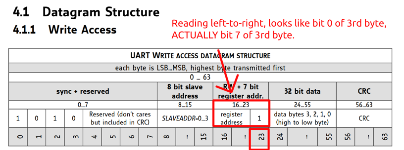
It clearly the bit order, but my mind still interpreted the picture
incorrectly. I also think because I kept comparing this UART protocol
to a poor-man’s I2C interface where the read/write bit is indeed the
Least Significant Bit, it added to my confusion. I decided that I
should send the read address with (addr << 1) and the write address
with (addr << 1) + 1. Looking at the middle entry this seemed
correct reading left-to-right, but looking at the section listing with
bits, this is clearly wrong. The correct read address is just
addr and the correct write address is addr + 128 to set the HIGH
bit to 1.
Stall Detection
With the UART enabled I was ready to tackle stall detection. This took a lot of trial and error to get right. One thing that’s annoying about the datasheets that come with many chips, is that they have 100’s of pages, and are very exhaustive, but they still don’t tell you how to do the things you actually want to do.
In this case I want a stall to throw the DIAG pin high so I can
catch it. I was left with this chart:
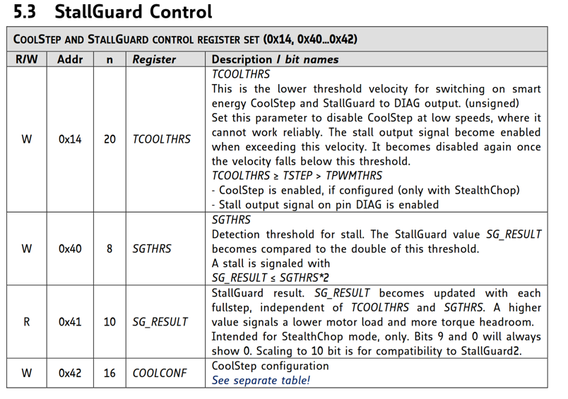
And it seemed like I needed to just set 0x40 to an appropriate value
and it would magically work. I tried high values, I tried low values,
I tried middle values, still nothing. After some googling I found some
working reference code. I learned I also needed to set the first
register in the section (0x14) to enable all the StallGuard
capabilities. My reading of the section made it sound like you only
needed to set 0x14 to disable functionality in some cases, but
you also need to set it to enable it in other cases.
In any case I was able to get working stall detection with some randomly picked values for both registers. Once I’m further along I’ll go back to the datasheet and try to calculate some smarter values for those registers.
UART Mode - Device ID assignment
The UART mode does support having up to 4 TMC2209 chips on the same bus. In theory you set each one to a unique device ID that is included in the register requests. Unfortunately this chip reuses the same two pins that are used to determine the amount of sub-steps that the driver provides.
If you want two motors to have the same stepping speed on the same UART bus, you need to either:
-
Add in some sort of external switching network to activate and deactivate connections to the UART pins. Or,
-
Make sure the motors aren’t enabled and getting step signals, change the pin states on each to give them different addresses, send the appropriate commands, then restore the old state back to the desired step level.
I went with option two which meant I needed to use 4 more GPIO pins on the Pi Pico. That took me to a total of 12 GPIO pins just for these two chips GPIO requirements, and 2 more for the UART connection.
Pi Pico software
I started running my tests on a Pi Pico somewhere in the middle of testing out UART. I just wrote simple test code to exercise all of the functionality. I was able to hook up two steppers with lead screws and do some basic exercising of the motors and stall sensing.
Currently the code sets up the stall detection and then provides a function to move up or down X number or mm at a rate of Y mm per second. It’s good enough to write proof of concept homing/leveling code and test movement.
Next steps
I’ve gotten as far as a Pico program that provides enough control to test. But my test setup is getting really messy.
There are many problems with my current breadboard:
- My breadboard is getting to be a real mess.
- Having a bench power supply for the motors is annoying.
- I had to hot-glue down the JST-XH plugs that hold the servo connectors since they only sort of fit in to the breadboard and would pop out.
- I needed to plug and unplug the USB on my Pi Pico to reboot the device to deploy and run code again.
- Wires everywhere, afraid I’m going to somehow mess up the setup when I don’t notice a wire coming loose.
This is all getting in the way of working on the software development. I want to build out a dev PCB to eliminate most of these problems. This will make things a lot less fragile, and will add some features to make it easier for me to redeploy and test code quickly.
All cad files, electronic files, source code, etc, referenced in this post series is available on my github page.