KC3MLC's Magloop for Amateur Radio
I finally built my own MagLoop and wanted to share plans, build tips, theory, and performance with everyone else who is thinking about trying to make one.
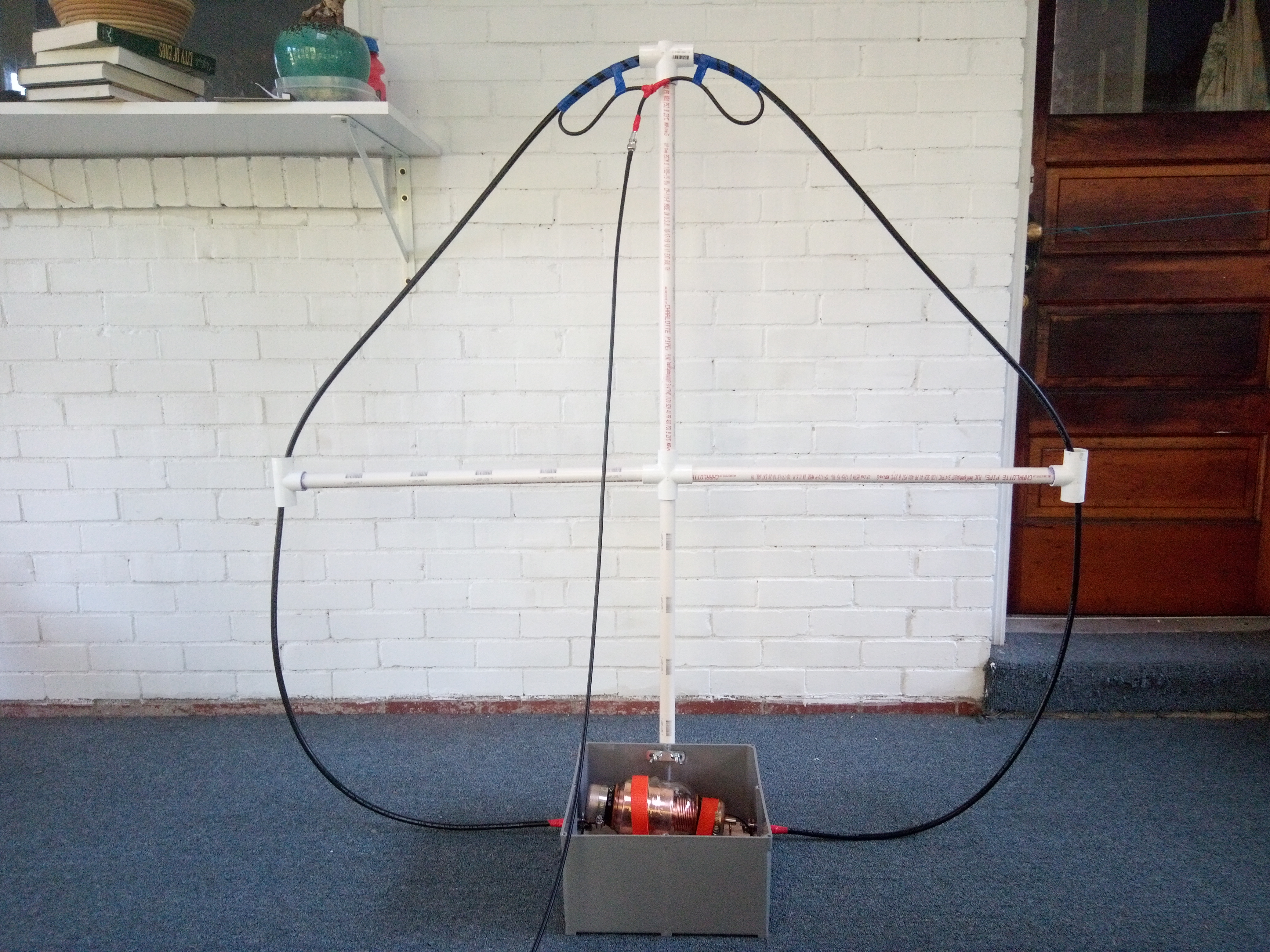
The design is moderately portable and defaults to a 4 foot diameter loop. In addition, the loop can be swapped out for a smaller 2 foot loop to work higher frequencies up to 10 meters, and a larger 8 foot loop to get better efficiency on 30-80 meters.
I’ve made plenty of FT-8 contacts from 15 to 80 meters on four continents (mine included) and have been happy with the results. I hope someone else can find it useful too.
Want to skip ahead?
Basic Magloop Theory
One problem I had while learning about magloops was that things just didn’t make sense! Everything I’ve read before said loop antennas need to be 1 wavelength loops, 1/2 wavelength dipoles, and 1/4 wavelength verticals with ground radials. How on earth can a loop that’s only 1/8th to 1/4th a wavelength, fed by another element that’s 1/5th the size of that (so 1/40th to 1/20th of a wavelength) even work at all?
Lets get the very brief theory of operation out of the way as painlessly as possible:
Start with the main loop. You have a single loop of wire attached to a capacitor opposite the driven element. We know that a coil of wire creates an inductor. In this case the loop is a coil with exactly one turn and is indeed an inductor! Combined with the capacitor, we now have a LC circuit which will resonate at appropriate frequencies.
Next up is the driven element, the loop of wire connected to your transmitter and placed inside the main loop. Once again, even though this is a single loop, it’s also a 1 loop coil of wire, making it another inductor. And what happens when you place two coils of wire next to each other? You get a transformer. The driven element puts out the RF energy, where it is transferred to the loop, and we have radio waves.
Hopefully that makes things seem slightly less mysterious.
Design Goals and Decisions
It All Begins With an Absurdly Large Capacitor!
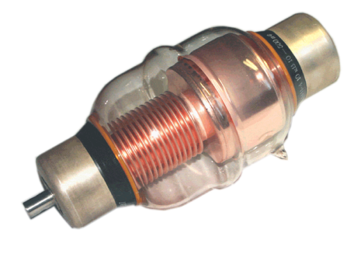
As I read up on literature and ran through online magloop calculators, a recurring theme is that a magloop can generate extremely high voltages, 3000-5000 volts and more! A standard air variable capacitor, where you rotate two sets of metal plates, can’t handle those voltages with even moderate power. This isn’t just a case of the literature being overly conservative. A previous magloop I build with such a capacitor would generate blue electric arcs when my transmitter hit even 15 to 20 watts.
I’m only planning to run 100 watts, but needed a capacitor that could handle more power. I needed a vaccum-sealed capacitor which removes the easy path for high voltage electric arcs between plates. The best way to get one that can do this and is affordable to the hobbyist is to order old Soviet-Era surplus vacuum variable capacitors off of eBay.
As I browsed the various listings from sellers in Ukraine and the Russian Federation, I kept up-selling myself. Only $10 more to handle 10,000 volts! Sold! Only another $20 for another 100 picoFarads! Done! And before I knew it I had purchased the biggest monstrosity of a variable capacitor that the finest minds in Soviet engineering could produce: A 10-500 picoFarad capacitor with a 10,000 kV rating. I didn’t realize how big I had gone until the thing arrived. It was huge! 10 inches long, five inches wide each way, and weight in the range of 6 pounds!
This forced me to change my initial design. Most loop builders indicate that they’ve gotten better results with the capacitor at the top of the loop and the driven element at the bottom. That was out based on the weight. And I originally hoped to get some height off the ground with a simple mast or tripod. Things would also be too top heavy for that.
I decided to turn the size of the capacitor from a weakness to a strength. Instead of attaching to a mast, I would create a base unit that could stand on its own. The weight of the capacitor itself would help stabilize the antenna. The base could then be placed on a picnic table, the roof of a parked car, or even an upside down bucket for actual usage.
Portable
I wanted my design to be portable in several ways. Many designs out there involve making an 8 or 16 foot high octagon out of copper pipe that has been braised together! I wanted something that I could throw in to my car and hopefully try a POTA excursion one day. And I at least wanted to be able to get the thing inside my house or garage without having to take a cutting torch to it!
Based on this, the main loop is just good old RG-213 coax with the shield acting as the loop. I can coil up the loop when not in use. As an added bonus, this allowed me to make different swappable variations of loop sizes easily.
Temporary
This antenna is intended to be used on site temporarily. It’s not intended to be mounted permanently. As such I tried to make it a little weather resistant in case there’s some light rain, but made no attempt to make it fully water or wind proof. If storms are coming the antenna goes inside.
No Motors
Many designs include a motor that spins the tuning capacitor at a distance. Some include a rotator to take advantage of the antenna directionality.
I had serious problems with a motor attached to a smaller capacitor on a previous antenna. It caused all kinds of stray capacitance and bizarre changes to SWR at random inexplicable times. I didn’t know if it was the control cable for the motor, the coils of wire in the motor, the connection to the capacitor, or what.
For now I will tune the antenna by hand, and position it by hand. This can be a little annoying, but I don’t intend to hunt-and-seek contacts. I plan to sit on a frequency, such as an FT8 frequency, or possibly calling CQ on a single frequency in a future POTA excursion. And running FT8 has worked just fine.
I’ll probable reconsider this at some point, but at least then I will have a good handle on my baseline expectations for the antenna and a better feel for if and what problems are caused by a new motorized attachment.
Build
Capacitor Mounting and Base
As I mentioned, when my capacitor from Ukraine arrived after six long weeks, it was bigger than I expected by far! But I was ready to get to work. So I went to my local big box hardware store and found a 12 inch by 12 inch plastic electrical junction box. If I had been more patient, I probably could have found something cheaper.
To make the basic base first mount the SO-239 adapters:
- Mark the centers of the adapters on the outside of the base.
- Drill pilot holes.
- Drill out the large holes until the threaded part of the SO-239 can fit through them.
- Insert the adapter through the hole backwards, so it faces inside the case. Mark the location of the four mounting holes in the adapter. Remove the adapter.
- Drill the mounting holes.
- Place the adapters in the correct way and mount them with nuts and bolts.
- Use one extra long bolt on each adapter so you can eventually wire up the capacitor.
ProTip™: If you’re starting to make a bunch of amateur radio gear and you don’t have a STEP DRILL BIT you’ll want to get one as soon as possible. It allows you to drill large holes for things like SO-239 adapters without having to switch out bits repeatedly and without melting ABS plastic. A set is a few dollars and probably available at your local Harbor Freight.
 To make the support holder:
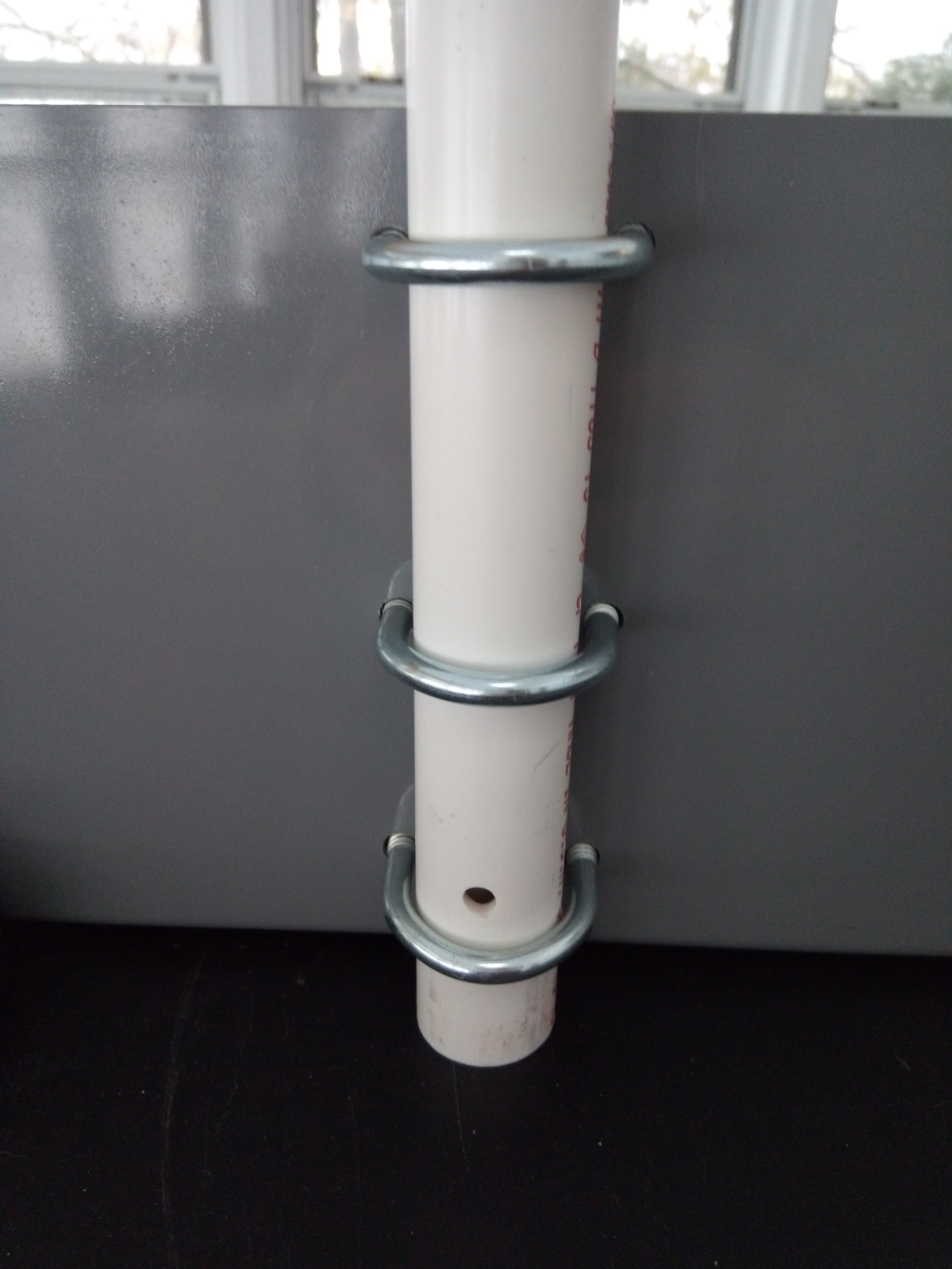
- Drill three sets of holes: top, middle, and bottom, that will each fit a 1 inch U-bolt.
- Insert the U-Bolts and thread them in from the inside.
To attach the capacitor:
- Cut two 8-inch lengths of 14 Gauge insulated stranded wire.
- Strip a 1/2 inch or so off of each wire.
- On the long bolt on each adapter:
- Add one washer.
- Wrap the exposed wire around.
- Add another washer.
- Add another bolt and tighten to get a good connection.
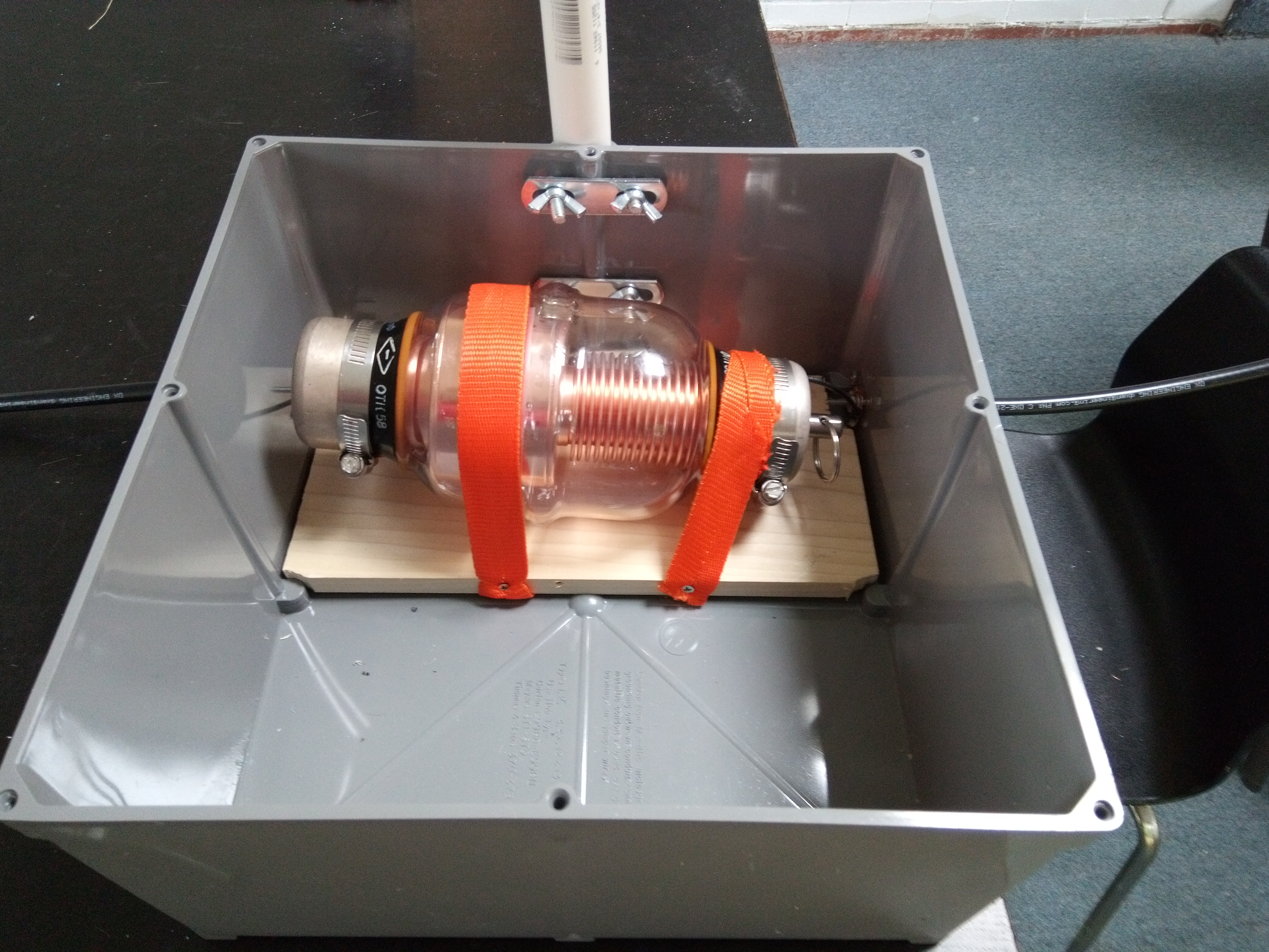
- Take two hose clamps and put them on the ends of the capacitor. Screw them down until there’s a half inch of slack.
- Place the capacitor in the base and position it.
- Trim and strip the other ends of the 14 gauge wires so that they will reach the capacitor and have enough stripped wire to wrap around the hose clamps twice.
- Remove hose clamps from the capacitor, wrap the wire around twice, re-attach and screw them down to get good contact between the wire and capacitor.
This completes a usable base.
This was enough to start using things, but it eventually became frustrating to tune the capacitor as it wobbled around. To reduce the wobbling, I bought a piece of 6 inch wood, and cut it it fit inside the box. I then used some old nylon straps to secure the capacitor to the board with a few screws.
ProTip™: Often times when you’re reading antenna plans you’ll be presented with a detailed manifest and list of parts. This is nice to be exhaustive, but often times leads to the impression that certain parts were carefully spec’ed out and tested, rather than just being materials available to the author.
The wooden base for my capacitor is just such a thing. It was wobbling, I wanted to stop it, and I didn’t want to use metal or drill holes in the exterior case. This was the solution I came up with. If I had a 3D printer I probably would have come up with something better. I’m hesitant to give detailed instructions since it was hacked together.
In short, feel free to improvise with any element of the plans presented here, and particularly with the capacitor support which I just threw together in a weekend. Even now I find myself wondering if I could make a base out of a beer cooler that’s big enough to hold all the cables and supports.
PVC Supports
 I
made a set of composable PVC support
pipes that would allow me to
easily set up loops of either 2, 4, or 8 foot diameters. My big box
hardware store had pre-cut 2 foot sections of pipe, and I went for
this rather than cut them myself. I also bought adapters to get the
following combinations. The pipes were 3/4 inch and had an outer
diameter of 1 inch.
I
made a set of composable PVC support
pipes that would allow me to
easily set up loops of either 2, 4, or 8 foot diameters. My big box
hardware store had pre-cut 2 foot sections of pipe, and I went for
this rather than cut them myself. I also bought adapters to get the
following combinations. The pipes were 3/4 inch and had an outer
diameter of 1 inch.
-
One pipe with a four way adapter attached to one end which I’ll refer to as the crossbeam.
-
Two pipes with T adapters to support the sides of the RG-213 loop which I’ll refer to as the side supports.
-
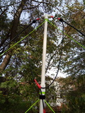
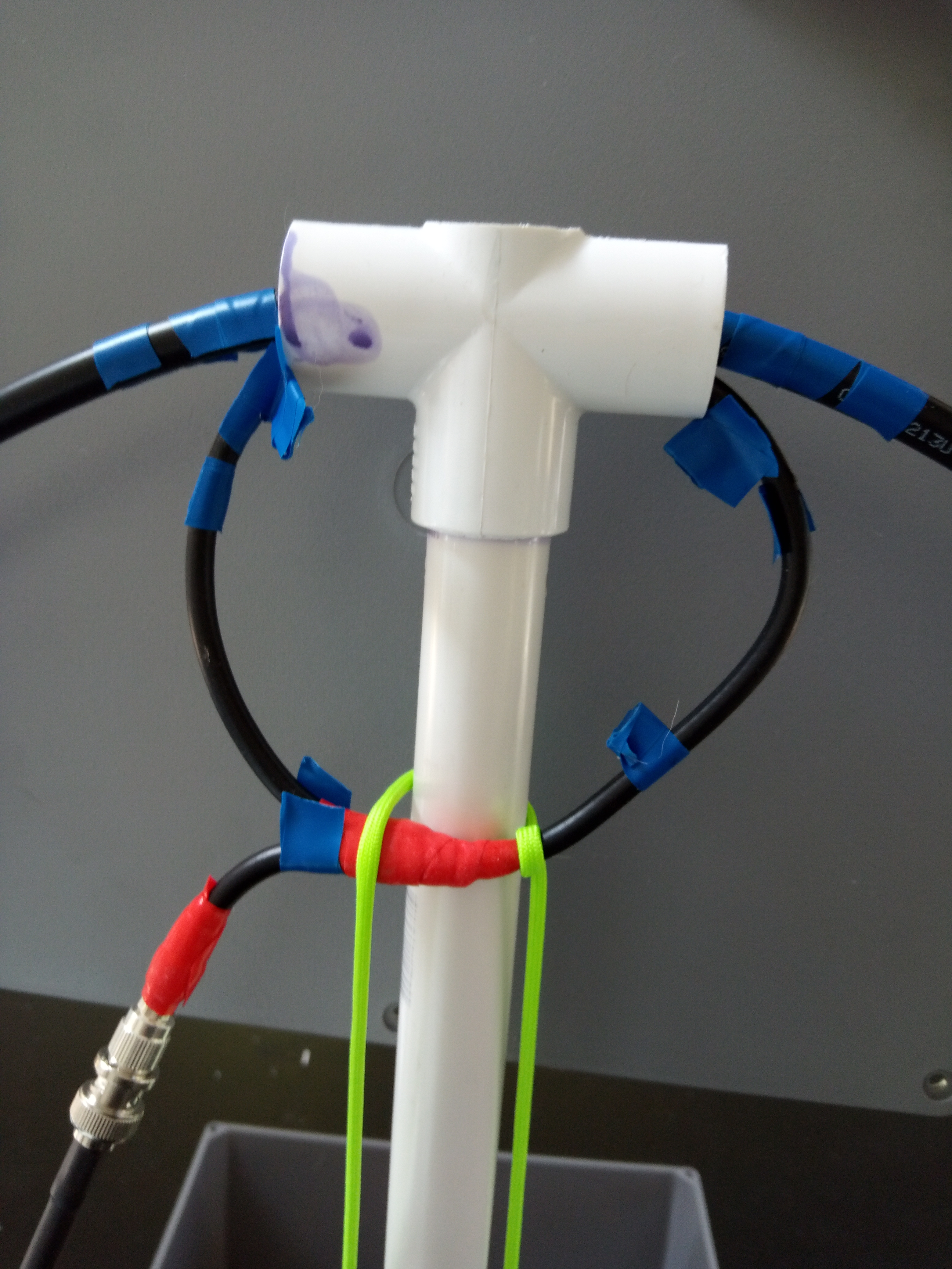
 One pipe with a modified T adapter to support the top of the loop
which I’ll refer to as the top support. A
slot was cut in to this so the main loop, along with the driven
element could be hung on the adapter without having to pass through
it. To do this I put the adapter in a vice and cut it with a hacksaw
before attaching it to the pipe section.
One pipe with a modified T adapter to support the top of the loop
which I’ll refer to as the top support. A
slot was cut in to this so the main loop, along with the driven
element could be hung on the adapter without having to pass through
it. To do this I put the adapter in a vice and cut it with a hacksaw
before attaching it to the pipe section. -
Four pipes with a standard coupling attached to one end which I’ll refer to as the extensions. extenders.
The attachments were glued on with PVC primer and glue so that when I disassemble the supports the right parts stay together and the wrong parts don’t get stuck.
ProTip™: DO THIS OUTSIDE! I made the mistake of doing this on our enclosed porch, and fumes still managed to pervade the entire first floor of our house. We had to open the windows and air it all out. It is highly recommended that you have more ventilation.
Loops
I will generally refer to the loops by diameter which is also the height of the PVC supports. These are nice round numbers where the actual size of the loop is diameter times Pi. In addition there is some amount subtracted from the ideal cable length to account for the area of the loop where the capacitor sits and there isn’t any wire.
The loops are made of RG-213 coax with PL-259 plugs attached at each end. This allows me to insert the loop into the support frame and screw it in to the base.
The actual cable length was:
- 2 Foot Loop - 5 foot, 9 inches
- 4 Foot Loop - 12 foot, 8 inches
- 8 Foot Loop - 23 foot, 6 inches
The 8 foot loop ended up being slightly shorter because it was drooping more, and I went with more of a diamond shaped loop to avoid this.
While building your own antenna, rather than measuring out to these lengths,you should attach a PL-259 adapter to one end of the coax, feet it through the supports and screw it in to one side of your base, and then mark off the appropriate place to cut the other end of the cable. This will give a better loop if your project box or SO-239 placement is different than mine.
Driven Elements
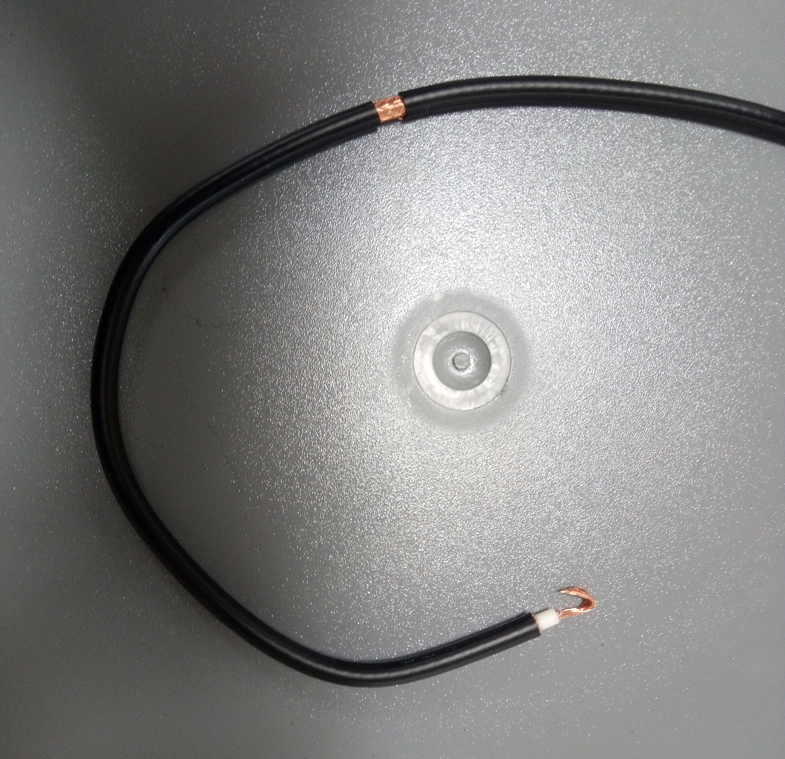
The driven elements are made from RG-8X and should be 1/5 the size of the main loop coax. I did not try to factor in the full loop size including capacitor and just used the physical coax length divided by 5. There also needs to be a connector to hook the driven element up to your feed line, so when you cut the cable add 6 to 8 inches or more depending on how confident you are about getting the coax stripped and adapter installed on the first try. I used a female BNC adaptor but feel free to use whatever adapter you want.
There are many confusing designs available1 for the driven element. In the end I chose the least confusing one. This involved soldering the center conductor of the coax to the shield where the loop will be the appropriate size.
To make one:
- Cut a cable with an extra 6 to 12 inches to mount a connector to the feedline.
- Strip one end of the coax with a standard stripping tool providing enough exposed center conductor to wrap around the cable.
- Cut away the exposed copper shield at the end so it doesn’t accidentally contact anything it shouldn’t.
-
Measure back to the appropriate length and carefully remove 1 cm of casing without damaging the copper shield.
I found It was best to score the jacket on each side creating visible cut lines without cutting all the way to the copper, cut a slot out between the two lines, and then peel the rest of the jacket off.
- Wrap the exposed center conductor around the exposed shield and solder it in place.
- Use silicone self-amalgamating tape to seal the connection. I imagine heat shrink tubing or electrical tape instead would also be fine.
- Connect a BNC Female connector or adapter of your choice to the exposed end.
Installation
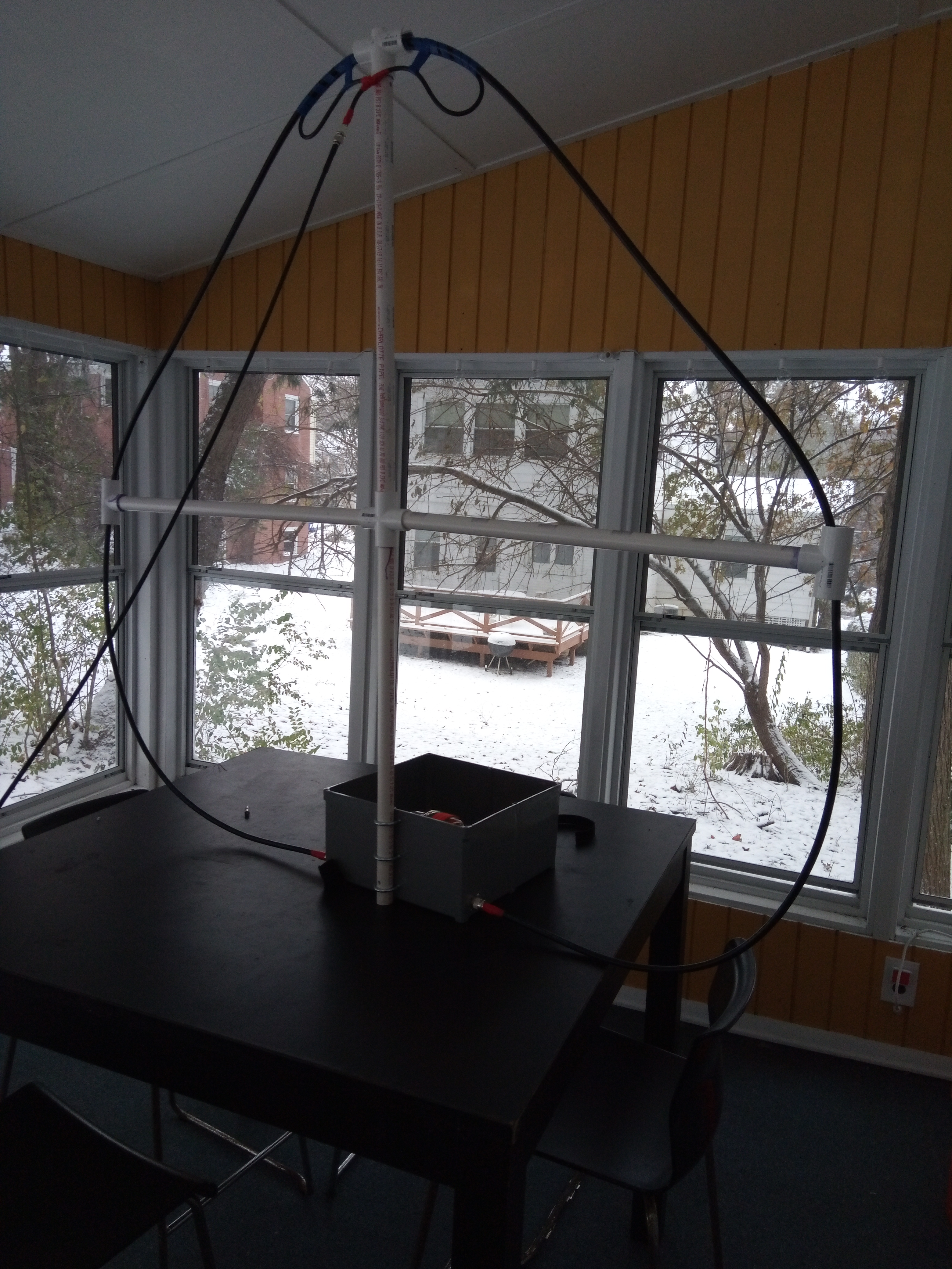
At this point you should be ready to do an initial smoke test. I would recommend using the 4 foot antenna and setting the assembly on a table in your shack before trying to use it outside.
Setting up the antenna
I would suggest starting with the 4 foot loop, which can get good reception on 20, 40, and 80 meters. I would also suggest using a workspace such as a table in your hamshack since it will take some time to perform initial configuration of the driven element. Once the driven element is configured it will be easier to set up in a more desirable location.
To assemble in 4 foot mode:
- Add the two side supports and top support to the crossbeam.
- Insert the crossbeam in to the U bolts and tighten the wing nuts to hold it in place.
- Hang the loop cable inside the top support, and thread the ends through the side supports.
- Screw the PL-259 connectors in to the base unit.
- Attach the feed line to the driven element.
Initial configuration the first time only:
- Insert the driven element in to the top support under the main loop.
- Use an antenna analyzer to roughly adjust the tuning capacitor to the desired frequency.
- Experiment with positioning as described in the tuning section securing the driven element with temporary tape.
- Once you find a workable position, permanently tape it the driven element to the main loop in a way both pieces of coax can easily be placed on the top support.
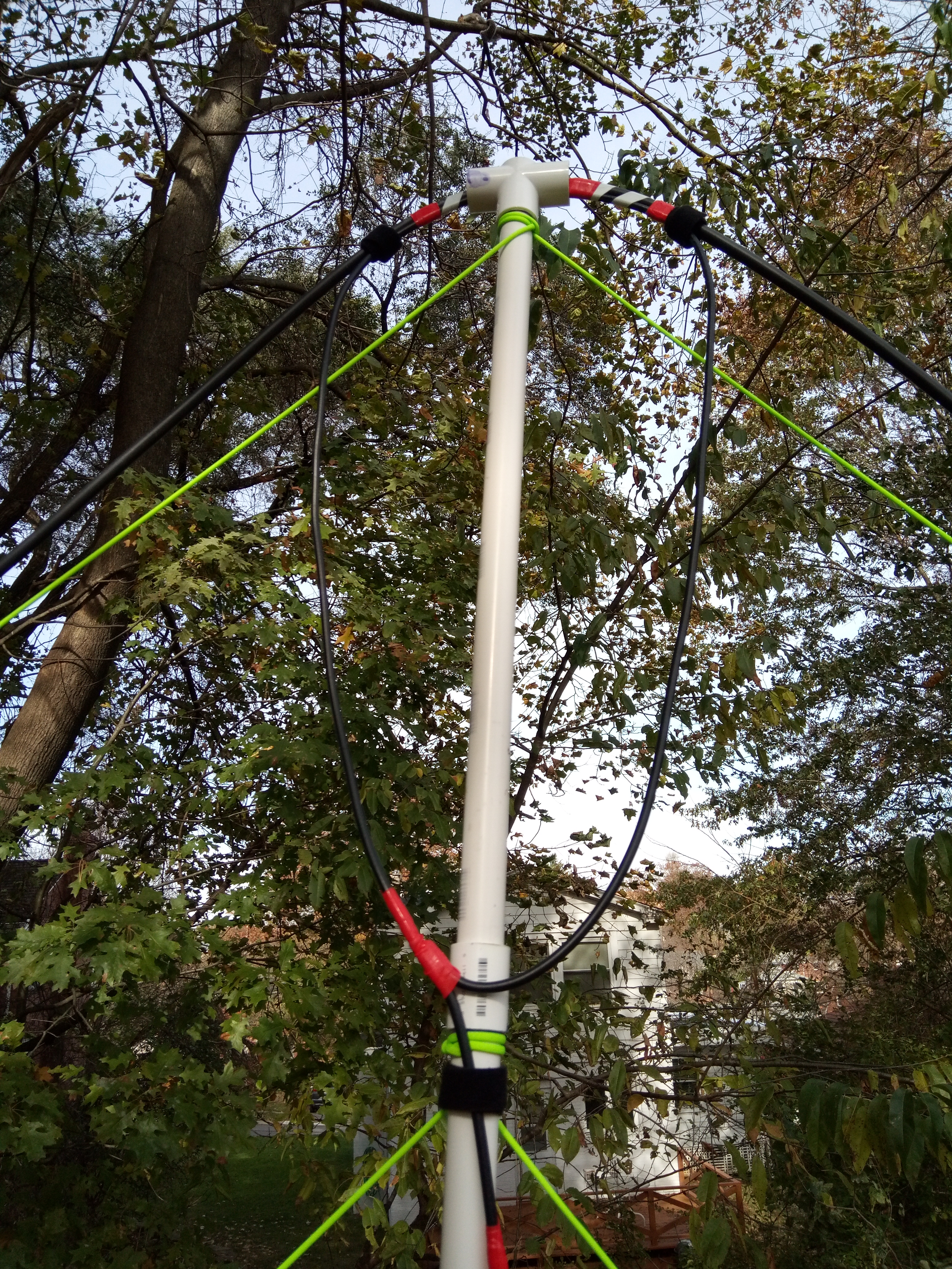
It should loop like this:
After initial testing you may want to set up the two foot loop. The procedure is basically the same, but you’ll use the Top Support only on the base:
Positioning
To get lowest SWR, the loop must be off of the ground. While testing on my back porch, I just sat it on a bar-height table. When I use the antenna outside, I set it on an upside-down utility bucket which is about 18 inches high. Any lower than that and the SWR started creeping up again. I suspect even higher is still better, as you’ll get better angles for DX takeoff, but the bucket was adequate to hit Europe and South America from Pittsburgh.
The antenna also has some directionality, with the strongest signal shooting off of the ends of the loop. It’s only somewhat directional, so I generally just point it either North/South or East/West and don’t try to dial in on an exact bearing.
Tuning
Tuning the Capacitor
Initial tuning is done by adjusting the variable capacitor. I attached a key ring to mine to make it easier to turn. When the capacitor is fully retracted and has the least amount of capacitance, you’ll be closest to the ideal efficiency2 for the given loop size. At this point, very small changes in capacitance will have a large impact on the frequency sweet spot. As you add more capacitance and the frequency goes down, you’ll find that the bandwidth decreases and that you’ll need to move the capacitor more to move the optimal frequency.
Tuning the Driven Element
When you initially tune the antenna, you’ll probably have a poor best-case SWR. Once you’re within range of the frequency you want to transmit on, you’ll need to adjust the driven element positioning to get the best possible SWR. This is done through experimentation and in my experience relies on two factors:
- How much of the top of the driven element contacts the loop.
- How far up or down the bottom of the driven element is from the main loop.
You’ll need to experiment for yourself. Here are some notes on what worked for me. These are not intended to be prescriptive; you’ll need to find your own positioning. They will just give you a starting point for adjustments to try:
-
The driven elements should be close to the plane of the main loop, but don’t worry about the support pipes preventing you from getting that last 1/2 inch.
-
 My driven element for the 2 foot loop most resembles what you’ll see
in diagrams and is a nice round circle attached to the top of the
antenna. Even still, some movement up and down on the bottom half
helps as I switch between various bands.
My driven element for the 2 foot loop most resembles what you’ll see
in diagrams and is a nice round circle attached to the top of the
antenna. Even still, some movement up and down on the bottom half
helps as I switch between various bands. -
 My driven element for 4 foot worked best with the most surface area
possible attached to the main loop, and the bottom half located
extremely high, making a crescent shape.
My driven element for 4 foot worked best with the most surface area
possible attached to the main loop, and the bottom half located
extremely high, making a crescent shape. -
 The driven element for the 8 foot worked best
in a kite shape, with
barely any contact on the top of the loop. This also benefited from
adjusting the position of the bottom on different frequencies. In
general as the frequency goes down, pulling the bottom down helped
on both this and the two foot antenna.
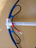
The driven element for the 8 foot worked best
in a kite shape, with
barely any contact on the top of the loop. This also benefited from
adjusting the position of the bottom on different frequencies. In
general as the frequency goes down, pulling the bottom down helped
on both this and the two foot antenna.As pictured, you can see velcro holding the loop in a position which is best for 40 and 80 meters, and I move it up for 30 meters.

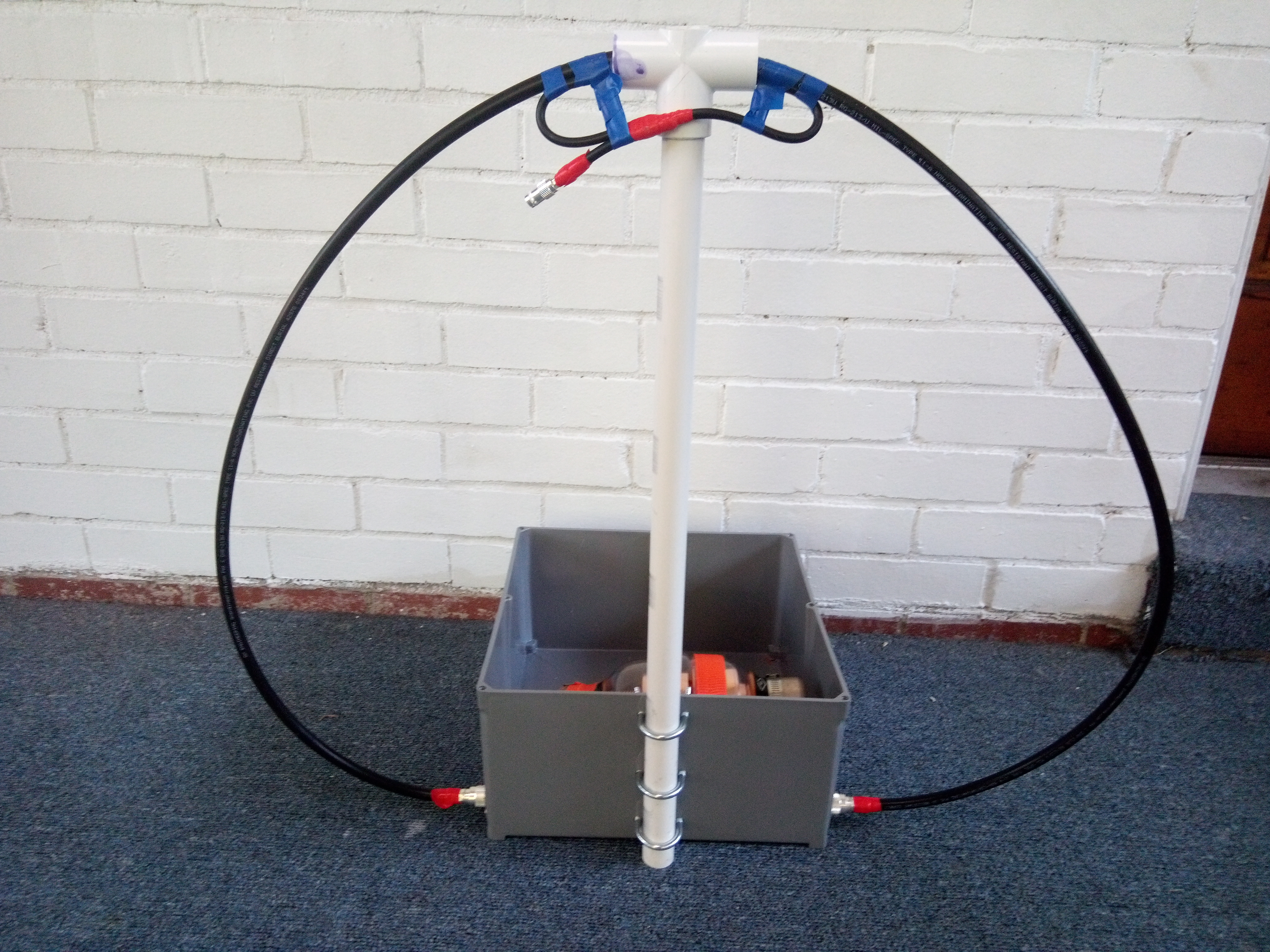
Setting up the 8 footer
Tension lines
The 8 foot loop requires both tension lines to hold the PVC supports in place. Drill 1/4 inch holes in the support element that could pass through paracord. Holes should be drilled through both sides of the pipe so the cord can be run through the pipe.
Hole Placement:
-
Side and Top Supports A hole close to and parallel with the T Adapters.
-
Crossbeam Support Two sets of holes, near the base with enough room for the extension element, perpendicular to each other with a half inch space between them.
-
Three Extensions One hole drilled all the way through near the coupling.
-
The Base Extension Two sets of holes like the crossbeam support, but located so that they are above the capacitor housing so it doesn’t interfere with the tension ropes.
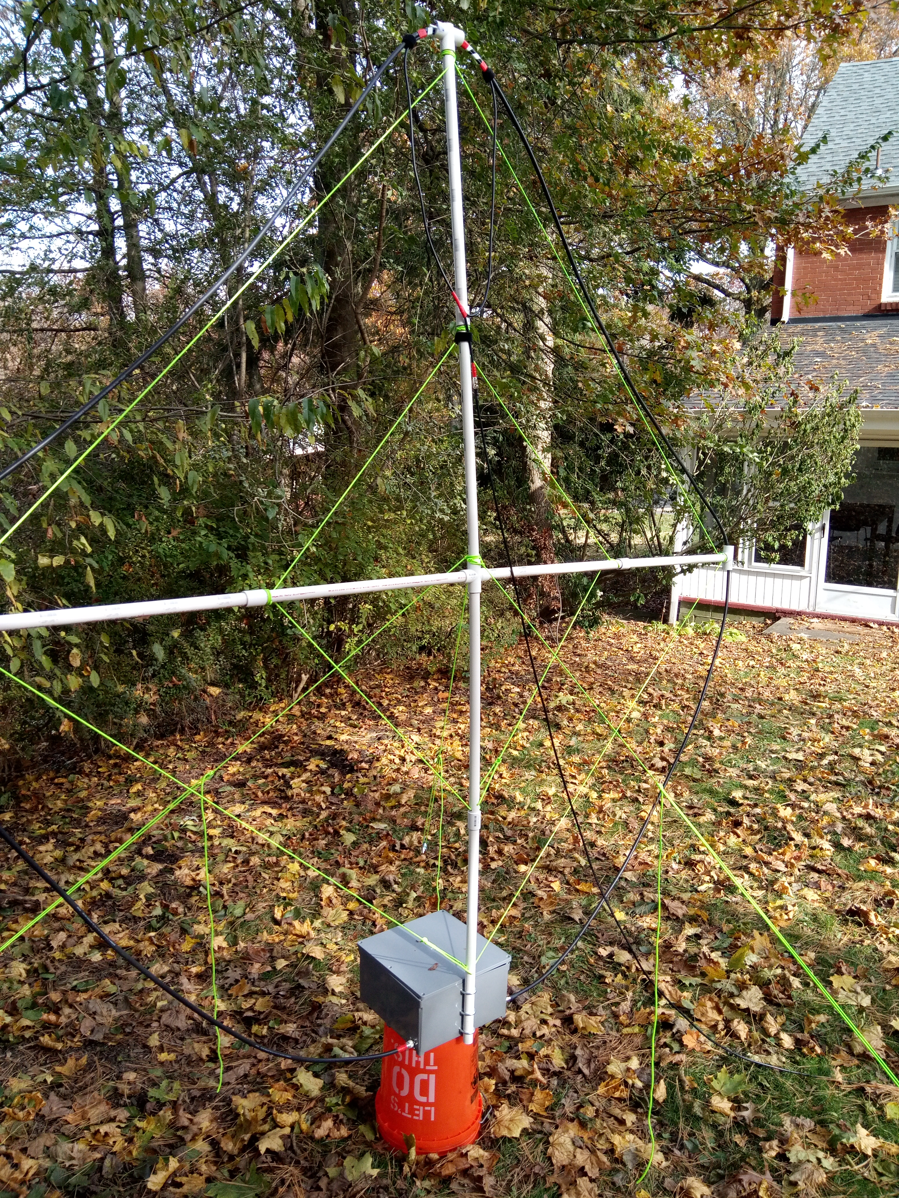
Review the picture of the assembled antenna if my placement directions don’t make sense.
Cut appropriate lengths of rope and melted the ends shut with a grill lighter. If you smell burning plastic and see smoke, you’ve melted them too much. Wrapping the cord around the pipe takes surprising amounts or cord, so start off with more cord than you think you’ll need and trim it back after your initial assembly.
First assemble the inner set of supports:
- Attach the crossbeam and three extensions with normally placed holes.
- Tie a knot in one end of the paracord and insert it through one set of holes at the base of the crossbeam.
- Work through the other three supports running the line through the hole, pulling it tight, and tying a clove hitch.
- Once these three supports are secure, run the line through the second set of holes on the crossbeam, tie a tautline hitch, and pull it tight.
The end supports can be attached and tied with the same procedure. It is best to (1) do this outdoors, and (2) only insert the supports one at a time as you’re ready to tie them in place.
Next mount the support in to the base and tighten down the U Bolts. Although you’ll need guy lines for long term installation, this will usually sit fine on flat land without tipping over. Still, release the supports slowly as you let go the first time.
ProTip™: Install the main loop and attach the driven element to the feed line before inserting the support in to the base.
Guy lines
The 8 foot loop also needs guy lines. To prepare the guy lines, cut paracord to three appropriate lengths, melt the ends closed, and tie a bowline knot on one end.
To install the guy lines loop them around the center mast, placed the antenna some sort of support, secure the lines to stakes with tautline hitches, and apply tension.
A helper is extremely useful here especially when the land is not flat, but you can usually find one line to secure first while holding it tight and then go back and get the other two lines in to place after the fact.
For the initial driven element configuration, you will probably also want a step stool to find optimal placement.
Performance
ProTip™: pskreporter.info provides a great way to see how your antenna is doing when you’re working digital modes. Various stations send signal reports to a centralized location where you can view how well things are propagating, even when people are ignoring your CQ calls.
Note that if you want to help out others and send your FT8 reception reports, you must enable this in WJST-X settings under Reporting.
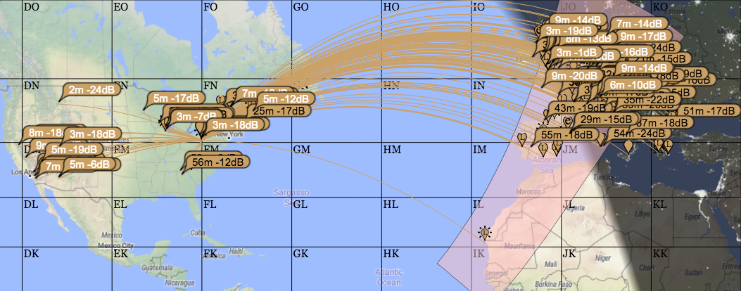
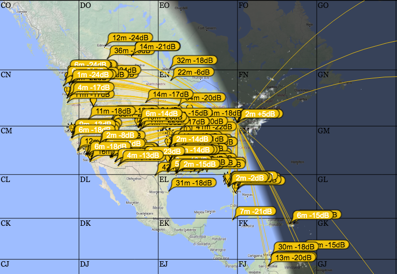
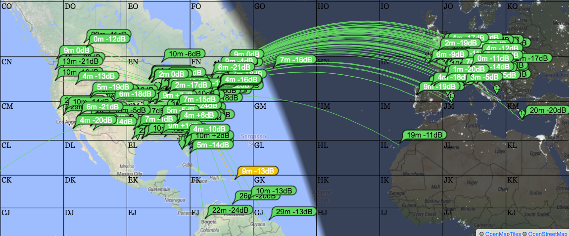
All results shown are from grid square EN90 running a Yaesu FT-857d at 100 Watts, operating in November 2019 in the deepest darkest reaches of the end of Solar Cycle 24.
| Band | ||
|---|---|---|
| 15 |
 2 Foot / North-South / Morning
QSOs with Germany, France, and Italy, along with a new DXCC entry at Bosnia-Herzegovina. |
|
| 20 |
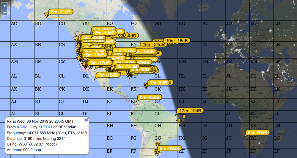 4 foot / North-South / Afternoon
First Alaska contact and a couple hits in Brazil. |
 2 foot / North_South / Dusk.
Not as bad as expected. |
| 30 |
 8 foot / East-West / Afternoon.
QSOs with Italy, Croatia, Crete, and the Balearic Islands. |
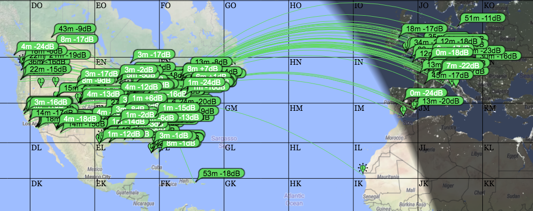 4 foot / NorthEast-SouthWest / Afternoon.
Pointing directly to London helps us getting to Europe, but still not as far inland as the 8 foot loop. |
| 40 |
 8 Foot / East-West / Morning.
We are getting further than ground-wave, but only high angles are making it back, giving an effective radius of somewhere between 750-1000 miles with a few outliers. |
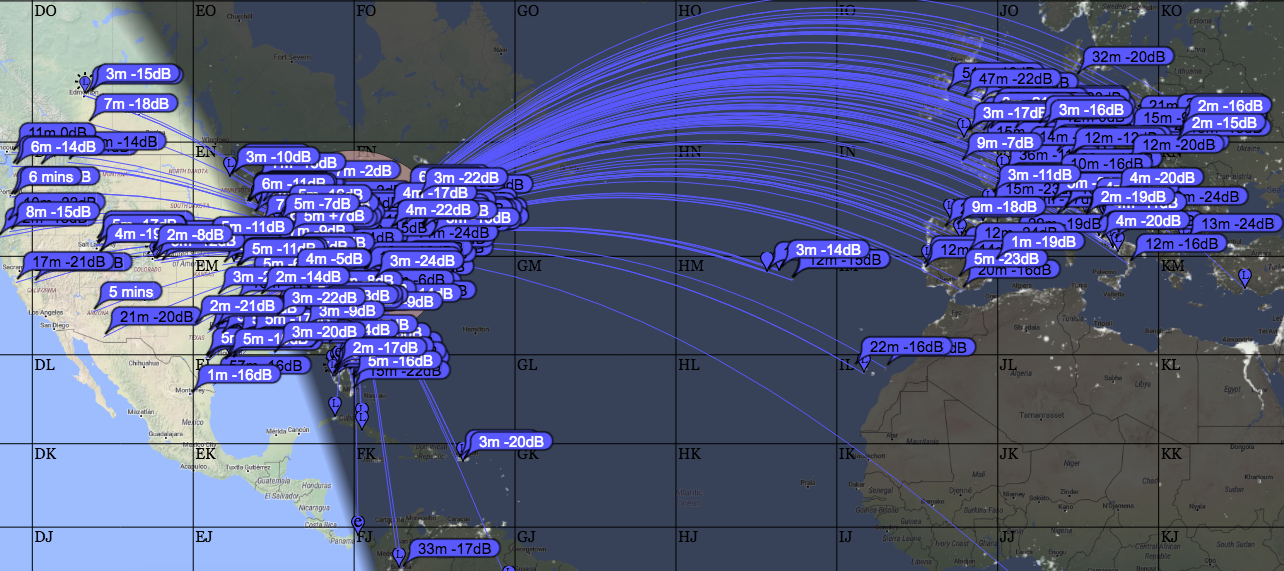 8 Foot / East-West / Sunset
Now we're seeing good results to Europe! |
| 80 |
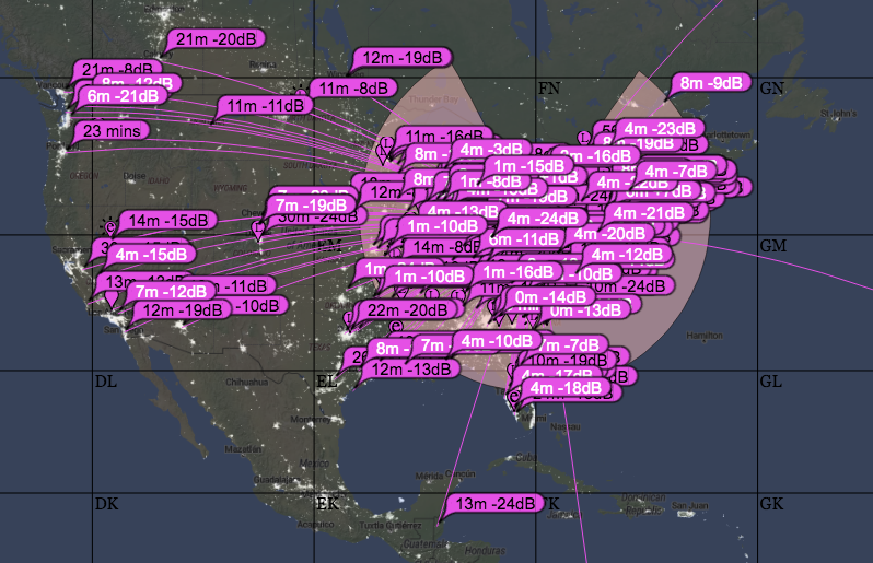 8 Foot / East-West / 10 PM
|
Reference
-
Inductive Coupling Designs This article has a wealth of information on all things magloop, with a particularly detailed description of various ways to drive the magloop. ↩
-
Online Efficiency Calculator and AA5TB’s Excel Application allow you to estimate how much of your power makes it to the airwaves for a given loop and frequency. ↩