Can Crusher Part 3 - Development PCBA
At this point I’ve built out the frame for my can crusher, and I wrote a proof of concept stepper motor control program with a Raspberry Pi Pico and TMC2209 stepper driver boards. But the board was getting very delicate and fragile and didn’t have all the features to make it easy to develop better software and do testing. I decided it was time to do round one of a proper PCBA to make it easier to move forward.
If I was actually building this for a company, there would be a good chance the hardware person would pass off the development to a firmware person, mechanical people would want test units, etc. A PCBA makes that a lot easier for all parties involved. In this case it’s just me, but it still makes my life much easier.
I’ll use KiCad for all the PCBA work.
Basic Design
I want a PCBA that could fit either in the base or top of the machine. That limits the size. In addition to that I want it to:
- Have a plug for the 12 Volt power supply that works with a normal power adapter instead of a bench supply.
- Have an easy way to reboot. I’m currently unplugging and plugging the USB cable to reboot and that is annoying.
- Optional Pico power supply pins to run without USB cable.
- Explicit enable of 12 volt power to the stepper subystem.
- Provide a UART control connection.
- Provide a very simple user interface with feedback.
- Expose any unused GPIO pins for additional features, such as a can sensor.
- Mostly use through hole parts.
Soft Reboot
This is easy enough. You just need to pull the RUN pin to ground. I
added a button that can be pressed to reboot.
12 Volt enable
The stepper controllers and motors draw a lot of current and can generate a lot of heat. I don’t want them doing that continuously if I accidentally leave the crusher plugged in while going away for the weekend.
I’ll build out a MOSFET switch that defaults to keeping the 12 volt supply OFF. It can only be explicitly enabled when a properly running program on the Pico does so. Rebooting, deploying bad code, sitting in bootloader mode, etc, should default to turning the power off.
UART Control
I’m testing a lot of different things at this point. I want to test
the hardware, software, and the actual functionality of crushing a
can. For the latter I thought it would be nice to have a mini language
where send over a UART connection with things like UP 20mm and
HOME. It can also return status updates like the current position of
the crushing platform, and if the motors have detected stalls. This
will let me test various crushing algorithms without having to
recompile code.
It also provides the opportunity to provide an advanced control computer later that can use the same control port to interact with that system. I could have a Single Board Computer with a fancy display, touch screen, bluetooth access, etc. Separating those functions out from the Real-Time functions of controlling the motors is also good system design.
Primitive UI
Once again I want help testing things out without having to either:
- Recompile.
- Or read log entries to get feedback.
I’ve added a very simple UI consisting of an RGB led and a single button. I can try to crush a can when the button is pressed. It can show a green light if things are good and red if the motors have stalled. Pressing the button again could cause the platform to lift itself back to the original position.
Nothing too sophisticated, and I might not even use it, but might as well throw it on since it’s cheap and I have GPIO pins to spare.
Expansion Port
Here I’ll just add a header with access to every unused GPIO pin, ground, and 3.3 volt power supply. This will allow me to add one or two more devices without having to make a new board. I still haven’t decided how the machine knows a can has been inserted.
Through hole parts
Lets keep things easy to assemble, and more importantly make it easier to modify a board if needed. I can handle the bigger SMT parts just fine on assembly, but often the first draft of a board will have one or two minor problems. Nice big holes on the board will make it easier to jury rig fixes.
Basic non-design
For now this is simple. In a final product I’ll want:
-
A buck converter to take 12 Volts to 4-5 volts to power the Pico directly. But I don’t know what chip I want to use so I’ll hold off.
-
A reverse polarity protection diode. This protects the board With a mis-wired power supply.
-
Capacitors, capacitors, capacitors? We should problably have a decoupling capacitor on the power supply. I’ve noticed 3d printer boards that take these stepper boards all have pretty big decpoupling capacitors as well. I need to review datasheets, do math, look at best practices etc, to pick the right ones.
-
A hard power switch.
I’ll deal with all that later.
From Idea to PCB
Getting a physical PCB made is surprisingly easy and affordable. There are manufacturers that get as low as $2-3 dollars for multiple copies of a simple circuit board. The shipping often costs more than the actual boards if you’re trying to get them quickly. If you’re a hobbyist and can wait a few weeks, there’s always the slow boat from China Post.
To get a board I need to:
- Design a schematic of the circuits you want.
- Export the netlist from the schematic in to the PCB editor.
- Lay out the parts in the PCB editor.
- Export ‘gerber’ files which tell machines how to do the board layout.
- Upload the gerber files to a manufacturers site, get a quote, pay.
- Wait for delivery.
The Schematic
I’ve whipped together some quick schematics before to get some simple boards built. Now that I’ve been professionally working with hardware for a bit, I’ve come to appreciate that the schematic isn’t just a prerequisite for PCB generation. It is the primary source of documentation of the hardware. If there’s an equivalent to source code for PCBs, as far as I’m concerned that’s the schematic.
“Programs must be written for people to read, and only incidentally for machines to execute.” Harold Abelson
And just like software, I’ve seen schematics that the author believed were self-documenting and intuitive when in actuality it wasn’t easy to understand the logic, what a sub-component was trying to accomplish, and why some little tricks were performed.
Although I feel this is a very simple board I went out of my way to try to focus on making the layout of the schematic clean and neat. I also used plenty of gulp words to explain functionality, even though that’s ultimately totally irrelevant to laying out the PCB.
In general things went smoothly with only a few complications.
Schematic Complication 1 - Missing symbols and footprints.
KiCad has a very large set of symbols for all sorts of resistors, capacitors, transistors, and chips. But it of course can’t have every part in existence. It was missing footprints for the Pi Pico (because it’s so new) and the BigTreeTech TMC2209 board (since it is a custom board). I needed to deal with that.
Luckily the Pi Pico is popular enough all the files I needed were available on github. But is still wasn’t quite perfect so I had to fork the code. My version is here.
There wasn’t even a starter for the BigTreeTech boards. I had never built out a symbol and footprint from scratch before so I was a little intimidated. Luckily it was pretty painless to do this. KiCad was set up to make it very easy to deal with any sort of chip or board that has a moderately normal configuration, such as the 2.54mm headers that the BigTreeTech board had.
Schematic Complication 2 - 12 Volt Enable Circuit
I wanted a circuit to explicitly enable the 12 volt power that gets to the stepper drivers and eventually the motors. As I mentioned above, I wanted it to be a safe switch, one where undefined or unexpected conditions caused it to not power the unit.
To complicate matters the stepper driver boards have two source of power coming in:
- The variable higher-voltage high-current motor supply.
- VDD for the logic levels.
Because of this I didn’t want to put the switch in the normal position (between the the boards and ground) because then there could be times where the chip was getting 3.3 volt VDD but wasn’t properly grounded. Instead I put the switch in front of the load (between +12 volts and the boards).
This meant using a P-Channel Mosfet. And since the Pico runs at 3.3 volts, which is a little too low to trigger a power mosfet, I needed to add another N-Channel mosfet switch. The basic design is:
- The Pico sets a GPIO pin to desired state.
- This activates a BS170 N-Channel mosfet which is happy with 3.3 volts.
- This in turn opens up an open drain circuit, dropping the voltage from 12 volts via a pull-up to ground.
- This opens up the P-Channel mosfet and the full current flows all the way to the stepper motors.
To make sure I got things right I did a mini test of this circuit only on a breadboard, two mosfets, one resistor, and a jumper wire.
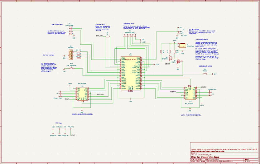
Schematic Results
Here’s the final schematic. Keep in mind that once I was in the PCB layout phase the process of PCB and schematic design was iterative. I’d realize I needed to change a pin layout and would go back to the schematic and edit and re-import to the PCB editor. This schematic isn’t the rough draft, it’s the first draft. For example, I inverted the Right Z-Axis Stepper Control schematic symbol to accommodate a good PCB layout and to keep my schematic clean.
PCB Layout
General PCB Layout Goals
In general there are a few goals any time you lay out a circuit board. In no particular order:
Minimizing PCB Layers. Traces connecting components can’t touch. They can’t cross paths. Eventually you get painted in to a corner and can’t connect two parts because there are traces in the way. The fix for this is to move the trace to a different PCB layer. The most obvious example is moving the trace from the top of the board to the bottom. But eventually that bottom layer might get filled up and you need to move to a 4 layer PCB design (or more) which increases production cost and board complexity. Based on the simplicity of my design I felt confident I could stick with a two layer board.
Organization of electronic components. If a datasheet for a chip recommends a capacitor on the power line you’ll want that close to the actual chip, not on the other side. If you have a differential pair of traces, like the D+ and D- signals of USB, should be next to each other. There may also be requirements to make traces between two components as short as possible. All these things need to be taken in to consideration when laying out the board.
Organization of other components. The power plug should be on the edge of the board. If you have light that shows that the unit is on, or a USB connector to program, those parts will also need to be on the edge.
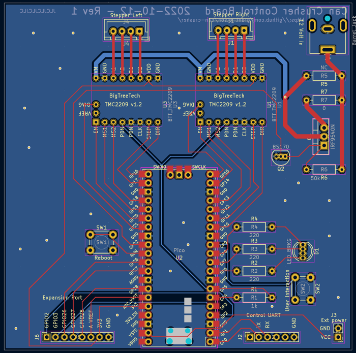
Laying Out the Can Crusher Board
When you start laying out the PCB it creates a rats-nest of parts. The program just drops them on the board with little lines indicating where parts need to be connected, but they’re a mess and they overlap. It’s up to you to figure out where to go from there.
The first issue that became apparent was that the pins I used to connect my Pi Pico to the TMC2209 boards on my breadboard were not ideal for the PCB. There were way too many crossed traces. I suspected this was going to be a problem on early drafts of the schematic, but decided not to sort it out until I could visualize the layout. Once I saw the parts and could position them on the board, it was easy to reassign the pins on my schematic and get a much cleaner bard layout.
The second issue was that I’ve never run power through a PCB before. KiCad has great defaults for microcontroller projects, but each stepper motor I have can draw up to 1.5 amps. That’s up to 3 amps total coming from the power supply. So what’s the problem?
A trace is just a flat wire. Just like wire, the size is only rated to carry a certain amount of power. If you go over that limit for too much for too long, the wire will heat up, burn up, or even melt! I found a reference chart and it recommended 0.76mm traces for 2 amps and 1.25mm traces for 3 amps. I increased the appropriate wire sizes. Then I had to reroute because the thickening the existing wires caused them to touch other wires and parts.
ProTip™: In the past I got very annoyed when I needed to move a trace in the PCB editor. KiCad treats each line segment as its own trace. I would always have to delete 5 line segments and would always miss the very small sub-trace that made the final connection to the component pad.
This popped up again when I was increasing trace sizes; selecting a trace, right clicking properties, etc, was annoying. After some google-fu I learned that I could select a sub-trace and then hit the u key a few times to expand the selection to include the rest of the traces in the network.
The last issue was that I wanted to take advantage of the silkscreen to make the board self documenting. Explaining which pins on the power header were positive and negative, explaining what GPIO pins we hooked in to on the expansion header, etc. It turned out KiCad has a pretty nice solution to this. If you choose Edit Footprint on an individual component in the PCB Editor if modifies that part only. You don’t need to edit the original footprint, or create a new official footprint in your library, just to have the right labels on an eight pin header.
In spite of all the issues it wasn’t too difficult to get things laid out, pass the DRC checks, and get a final version of revision 1 of the board. I was proud that I only had one trace that needed to jump from one side of the board to the other to avoid hitting other traces.
Ordering the PCB
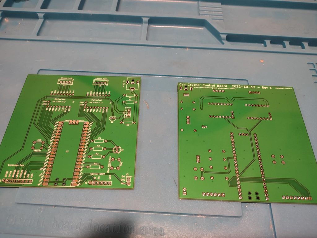
I ran a simple export of files from KiCad and sent them off to the vendor Wednesday afternoon EDT time. About 3-4 A.M. in China. They were able to manufacture the boards on Thursday and Friday their time, get things sent off to DHL, and somehow amazingly I received the boards on Monday by noon. Less than a week turnaround. Five boards total. Price of $3 for the boards and $19.05 was for the expedited shipping. It’s a great day and age to be a maker!
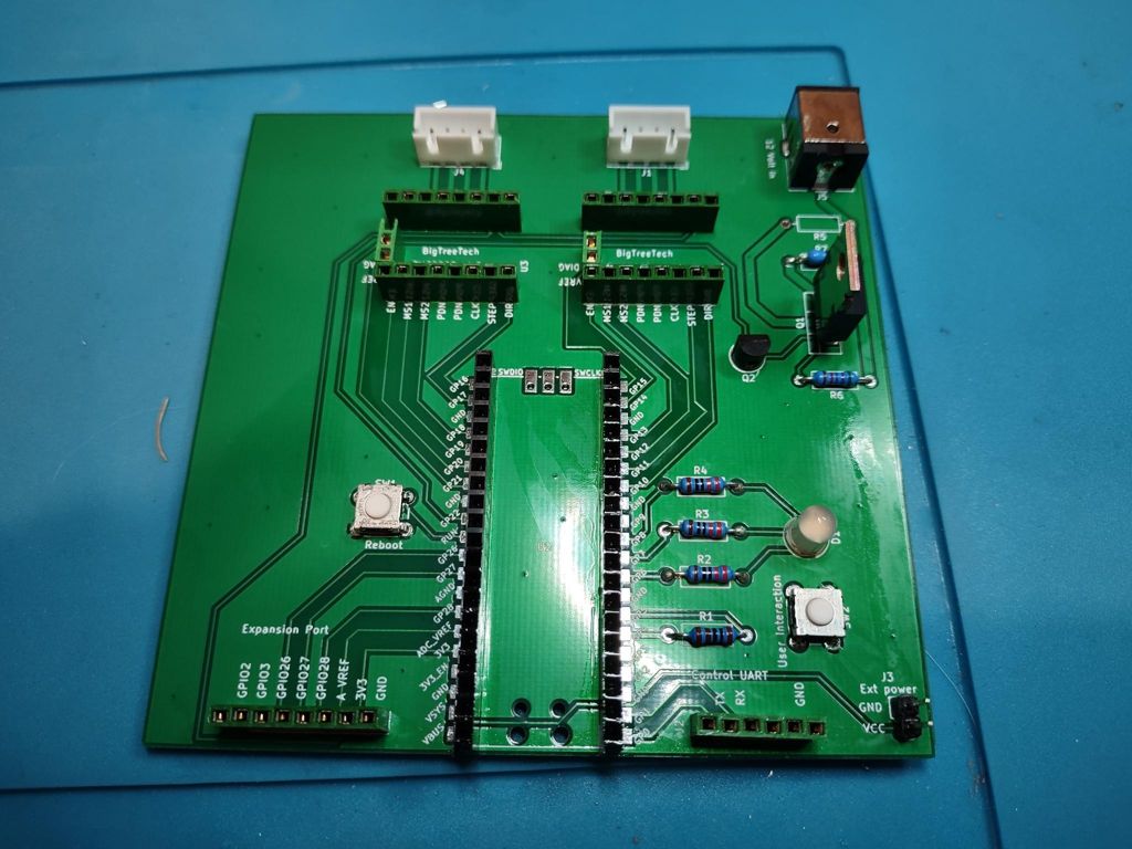
The unpopulated boards:
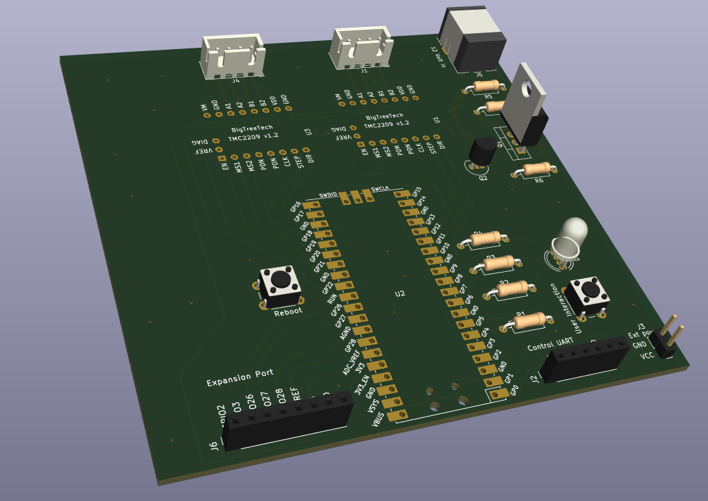
Assembly
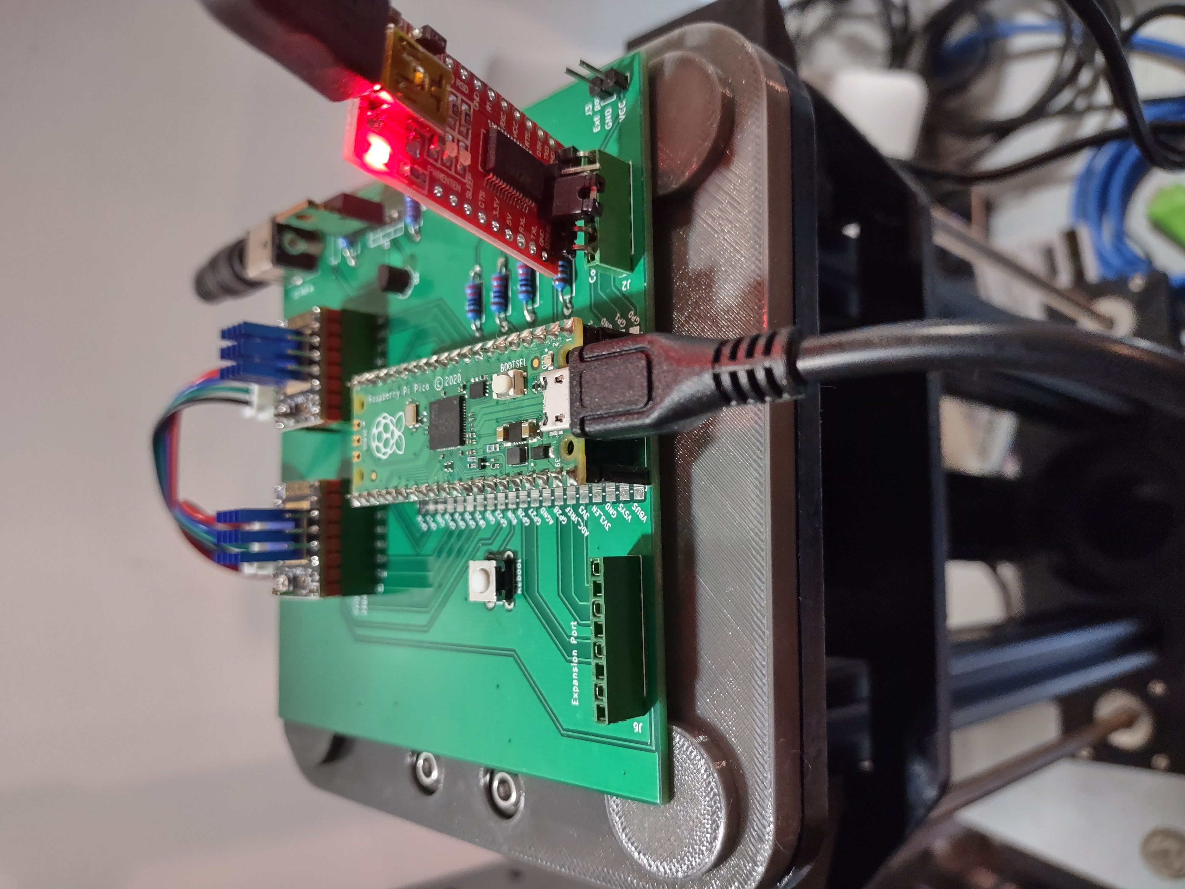
Assembly was straightforward. All the components were through hole. The footprint for the Pi Pico was nice. It was set up to use either headers, or solder directly to the board. For my test unit I added headers so I can swap the boards. This also allowed me to test the 12 Volt Power circuit one last time without inserting either the Pico or the TMC2209 boards.
Once testing was done it was easy to plug in the final components and start using the board.
Next Steps
The new board is working well and makes it much easier to push new versions of the firmware. However, it’s still pretty slow when I’m trying to exercise the range of motion, test sensorless homing, etc. My hard-coded scripts of action are too basic and then when I hit the base or the motors lose sync, I need to write a new hard-coded script to fix it.
To make things easier I’ll focus on adding a mini control language accessible via the UART port. Then I can test the actual movement without having to hard code a sequence of events in code base. This should make it easier for me to focus on algorithms for running the motors, find the right sensitivity settings for sensorless stalling, etc.
All cad files, electronic files, source code, etc, referenced in this post series is available on my github page.